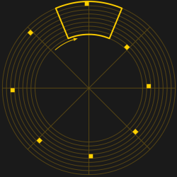
If you mis-spent your teenage years fishing broken televisions from dumpsters and either robbing them for parts or fixing them for the ability to watch The A Team upstairs rather than in the living room as I did, then it’s possible that you too will have developed a keen interest in analogue television technology. You’ll know your front porch from your blanking interval and your colour burst, you might say.

There was one piece of television technology that evaded a 1980s dumpster-diver, no 625-line PAL set from the 1970s was ever going to come close to the fascination of the earliest TV sets. Because instead of a CRT and its associated electronics, they featured a spinning disk with a spiral pattern of holes. These mechanical TV systems were quickly superseded in the 1930s by all-electronic systems, so of the very few sets manufactured only a fraction have survived the intervening decades.
The spinning disk in a mechanical TV is referred to as a Nipkow disk, after its inventor, [Paul Gottlieb Nipkow]. [Nipkow] conceived and patented the idea of a spinning disk with a spiral of holes to dissect an image sequentially into a series of lines in the 1880s, but without the benefit of the electronic amplification that would come a few decades later was unable to produce a viable system to demonstrate it. It would be in the 1920s before [John Logie Baird] would develop the first working television system using [Nipkow]’s invention.
![[Baird] with his invention, showing a large Nipkow disk. (Fair use).](https://hackaday.com/wp-content/uploads/2017/05/john_logie_baird_apparatus.jpg)
If the process is reversed and a lamp is placed behind the disk and fed an amplified video signal, as each hole passes in front of it there will be displayed a new line of the picture, and due to persistence of vision in the eye of the viewer the resulting fast-moving dot of light is built up into an image.

It is a given that a Hackaday reader is unlikely to stumble upon a Baird Televisor or other mechanical TV set. But the beauty of this technology is that a Nipkow disk is straightforward to make. The elementary school method involves marking a piece of card or similar flat material at the appropriate angles for the position of the holes and then measuring their position from the centre at each angle with a ruler, but a contemporary suggestion was to draw a spiral with the aid of a piece of piano wire wrapped round a central shaft. Alternatively Hackaday readers may wish to try creating a pattern for one programatically, this is the solution I opted for back when I was experimenting with Nipkow disks. My code – VBScript, but it was the 1990s! – has been lost in the mists of time, but it involved first drawing a ring of sync holes following a clock face demonstration script, then drawing another ring with appropriate decrease in distance from the centre for each hole. (Update in 2026 – I found a later PHP version, and ported it to OpenSCAD.)
Lest you imagine the Nipkow disks are an antiquated technology found only in museums and on the benches of mechanical TV enthusiasts, there is one field at the cutting edge of science in which they still play a part. Confocal microscopy is a technique in which a sample is scanned with a pinpoint of tightly focused light, to produce an extremely narrow depth of field and to reduce or eliminate reflections from out-of-focus parts of the sample. The Nipkow disk has been joined by laser scanning in this task, but retains an edge when a very low light intensity is required for a photosensitive sample.
An outdated method for producing low-resolution television is probably not something that will set every Hackaday reader’s pulse racing. But I’m sure I’ll not be the only member of our community with an interest in this direction. If I’ve just described you, then maybe it’s time to cut yourself a Nipkow disk, and post your mechanical TV set on hackaday.io.
Header image: H. G. Cisin [Public domain].


For a modern take on it with a whole lot of yelling at the screen, check out William Osman’s take on it. https://www.youtube.com/watch?v=R96TtG5FCTU
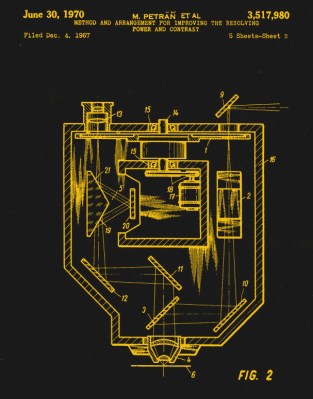
I like William Osman’s sense of humour and his projects are always interesting, even the bizarre ones. I wonder if a parabolic concentrator would improve the sensor performance? This sort allows the sensor to be placed so as to avoid a blind spot.
http://patentimages.storage.googleapis.com/US8058546B1/US08058546-20111115-D00000.png
Mechanical TV, the sound of the spinning disc, the humming of the motor, the blinking of the (too bright) lights that looked very dimm when looked through the holes of the disc. Ahhh… memories. As a kid I spend many hours trying to build something but due too the lack of materials and tools I failed every time. That was when I was 10-15 now I’m much older and have all the tools I need, all the parts I require. So last year I’ve build me a working 32-line televisor, fun, entertaining and very satisfying. It was my x-mas project, this year at x-mas I’ll try to improve it.
When I was a kid, info was only limited to books, today there is the internet and this wonderful world of information has brought me many insights in the many ways of how (mechanical) television could be achieved. I can highly recommend this forum on which many examples of projects can be found. But also lot’s of info about how the pioneers used to do this in the beginning of the previous century.
https://www.taswegian.com/NBTV/forum/viewforum.php?f=1&sid=a1e943c617325ba653adc0de38895e1b
Also this website can give many a good idea on how to start:
http://www.nbtv.wyenet.co.uk/
The website as mentioned at the beginning of this article, is certainly worth a visit as it contains lot’s of info and insights:
http://www.televisionexperimenters.com/home.html
Thanks!!!
Ooh, great links, thanks! televisionExperimenters has a nice write up of the Ediphor – wonder if there are any working examples of those out there?
Speaking of crazy and historic TV technologies, check out this crazy 3 gun projector. Beware X-rays!
http://www.myvintagetv.com/amphion_600.htm
Yay http://www.nbtv.org/
Also – using a square punch instead of a round one gives better SNR but its harder to make the punch. I’ve got one around here somewhere in alu.
Of course Lasercutters !
Hi Jan, the earliest surviving movie: Roundhay Garden Scene, just over two seconds, was filmed in 1888. First talkie On April 15, 1923, at the New York City’s Rivoli Theater.
In 1923, Eastman Kodak introduced a 16mm film
The Swiss company Paillard-Bolex SA introduced its first 8 mm camera in 1938 and its first ‘pocket’ 8 mm camera aimed squarely at the amateur market, the L-8, in 1942
How old are you?
I read the words “Nipkow disk”, clickbait title! :D
I wonder how many of these magnificent contraptions still exist. Would love to see one in person.
A modern take on Nipkow disk mechanical TV (in polish):
http://www.bsw.republika.pl/mechaniczny_tv.html
The concept seems similar enough to a POV display. Well, one where only a single LED could be on at a time.
Would the math to deal with the different linear velocities in a POV display be applicable here and be useful in chosing a hole pattern layout?
I made a crude near-IR viewer with a scanning disk many years ago. Light detected with an IR phototransistor on one side of the disk modulated a green LED 180 degrees away – the bonus was that it was always in sync. Performance was lousy, but it was a fun project to play with.
Awesome, could make one for UV!
For UV I would just project the image on a fluorescent screen with a lens.
You could try that with electrons even!
I’ve been wanting to make one of these for the last 27 years! This is where I heard of it first: Television Night https://goo.gl/GJ2wu7
At the time I just didn’t have the tools or resources. Now I’m pretty sure it wouldn’t be that hard of a project but more modern things like the 3d printer I am currently working on keep taking precedence.
I used a Nipkow spinning disk confocal microscope extensively in my PhD work. They’re clever devices for microscopy and have the advantage over a conventional laser-scanning confocal microscope in cost ($20-50k add-on instead of $200k) and speed (100s of Hz vs a few Hz).
Ultimate scanning speed is limited by the rotational speed of the disk, which is ~5000 rpm on the newer models. More pinholes in an array increase this speed as well, but also decrease the rejection of out-of-focus light.
The biggest draw-back for my work is that the light throughput SUCKS. Think a few percent of the potential throughput that actually makes it to the detector. If you have a lot of signal from your sample it’s manageable, but if you’re working towards the edge of detectable then it’s not good. There are other methods that win in terms of sensitivity there while allowing some sort of optical sectioning or rejection of out-of-focus planes, each with their own quirks.
You beat me to mention of confocal microscopes
I have made a televisor with the nbtv circuit boards, case is made from tufnel to look like bakelite and give a 30’s look, and a vintage volt meter for disk rpm, picture is very small but surprisingly good, holes done on miller with rotary table.
Tufnel?
Philo Farnsworth went to the UK and shared his information on his work on all electronic television with Baird, but Baird stubbornly stuck with trying to prefect his electromechanical system.
That sharing attitude would come back to bite Farnsworth when he showed Vladimir K. Zworykin around his lab in California, not suspecting he was a spy for RCA, looking to steal information on television so RCA could build it without paying Farnsworth royalties.
Philo was on What’s My Line, the old TV show. He said he “invented” electronic TV when he was 14. I would believe that he invented electronic TV based on the report that RCA was still working on a mechanical TV. Who invented TV may be as contentious a question as who invented radio.
We featured his appearance a while back. http://hackaday.com/2016/06/12/retrotechtacular-an-unexpected-meeting-with-philo-t-farnsworth/
One of my favorite Retrotechtaculars:
https://hackaday.com/2016/06/12/retrotechtacular-an-unexpected-meeting-with-philo-t-farnsworth/
He came to the idea of using a raster system, when he was 14, scanning from left to right and top to bottom. That made electronic TV possible.
There was one version of the Nipkow system that was even crazier than this.
The most straightforward way to create a video signal mechanically is to put the disk in front of the light sensor. But there was another method: the sensor is bare, and the studio is in darkness. Put the (much bigger) disk in front of the lights! The whole scene is scanned by the moving light beam–structured light from the 1920s.
I rather like the other alternative, the mirror drum. To mechanical TV what DLP is to digital TV.
The photo of Baird is fascinating…Is it just me or is that effectively an interlaced image? (Two spirals, with one offset halfway from the other?) But the holes seem awfully large, few (16 lines of resolution!) and close together (for a very tight image width, what 4″?)…Would love to see that unit in more detail.
I can’t comment on the interlacing, but I understand the large holes contain lenses.
Ah, I guess I don’t have a full understanding of the light path for this.
I did enjoy this page, which includes a YouTube video of a projection done in the ’60’s (and, again, it would have been cool to see more details as to how they generated the signal and more walkthrough of the mechanisms): http://www.telegraph.co.uk/technology/google/google-doodle/12121474/Who-invented-the-television-John-Logie-Baird-created-the-TV-in-1926.html
Great resource on the invention of modern television. Read it 20 years ago…
Tube: The Invention of Television by David E. Fisher and Marshall Jon Fisher
I guess you mean “Tube: The Invention of Television” by David E. Fisher and Marshall Jon Fisher
None of the inventors of television were not called “Fisher”.
The Grammar Nazi strikes again
Before home VCR’s it was a good thing for a TV repair shop to have a source of predictable video signals. B&K Dynascan made a flying-spot scanner that put out NTSC video. I’m sure there must still be some around somewhere.
Heck, I spent my teenage years dumpster diving for analog TVs and I’m only 22. The dream ain’t dead, folks.
The concept seems similar enough to a POV display. Well, one where only a single LED could be on at a time.
Another intresting website here, this time about baird’s attemps to record his pictures onto gramaphone records!
http://www.tvdawn.com/
ljones
Smells like day four? ;-)