The I/O capabilities built into most microcontrollers make it easy to measure the analog world. Say you want to build a data logger for temperature. All you need to do is get some kind of sensor that has a linear voltage output that represents the temperature range you need to monitor — zero to five volts representing 0° to 100°C, perhaps. Hook the sensor up to and analog input, whip up a little code, and you’re done. Easy stuff.
Now put a twist on it: you need to mount the sensor far from the microcontroller. The longer your wires, the bigger the voltage drop will be, until eventually your five-volt swing representing a 100° range is more like a one-volt swing. Plus your long sensor leads will act like a nice antenna to pick up all kinds of noise that’ll make digging a usable voltage signal off the line all the harder.
Luckily, industrial process engineers figured out how to deal with these problems a long time ago by using current loops for sensing and control. The most common standard is the 4-mA-to-20-mA current loop, and here we’ll take a look at how it came to be, how it works, and how you can leverage this basic process control technique for your microcontroller projects.
From Air to Electrons
The now standard 4-20 mA current loop for process control descends directly from an early innovation in industrial automation, pneumatic process control. Before electric controls were widespread, miles of pneumatic lines snaked through factories, providing not only the power to move actuators but also the ability to sense conditions. Process engineers used a pneumatic signaling system based on pressure — 3 PSI and one end of the sensing range, and 15 PSI at the other. Such a sensor would vary the pressure in the line based on the process variable, and could be used as input for a chart recorder, to directly control a valve, or even act in concert with other pneumatic sensors and actuators through sophisticated pneumatic logic controllers.
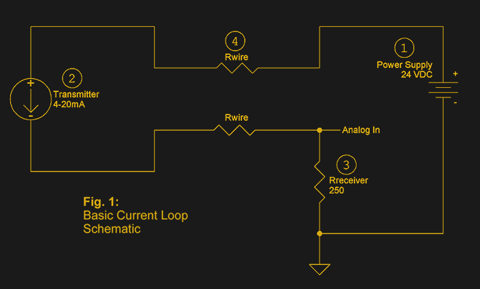
While pneumatic systems are very much still in use today, especially in industries where things tend to go boom around electricity, 4-20 mA current loop systems became a de facto standard in the 1940s and 1950s. In current loop systems, a transducer monitoring some process variable — temperature, pressure, flow, etc. — is connected to a transmitter. The transmitter is wired in series with a DC power supply — usually 24 volts in industrial settings. The transmitter is responsible for converting the output of the transducer into a current between 4 mA and 20 mA.
Kirchhoff’s Current Law tells us that the current will be the same at every point of the circuit no matter what the voltage is. So, if the voltage drops substantially because the wires to the transmitter are a half a mile long, or if the loop voltage varies because a huge motor started up somewhere else in the factory, it doesn’t matter — the transmitter keeps the current constant for a given process variable.
Current loops aren’t limited to sensors, of course. A wide range of actuators, from valves to motor drives, can be controlled by a 4-20 mA loop. Data acquisition and display are also possible, with chart recorders, gauges, and indicators all available for the loop.
But why is 4 mA — or 3 PSI, for that matter — the lower limit of the loop, rather than zero? Easy: because it provides inherent error detection. If the bottom value of the loop current had been set to zero, it would be impossible to tell the difference between a legitimate lower limit reading on a sensor and a broken loop wire.
One Resistor
So how do you incorporate a 4-20 mA device into your latest Arduino project? Changing the current back to a voltage by putting a resistor in the loop and measuring the voltage drop across it is really all it takes. [AvE] does the math to show us that a 250-ohm resistor gives us a one-volt to five-volt swing, which is perfect for an Arduino’s analog input in the video below (warning — slightly NSFW language ahead).
You might not have as ready access to current loop sensors and actuators as someone who works in industrial automation, and your project might not really take advantage of all the 4-20 mA standard has to offer. But it’s nice to know it’s there when and if you need it.


OR just use a digital sensor
https://www.digikey.com/product-detail/en/DS18B20+PAR/DS18B20+PAR-ND/1197285?WT.mc_id=IQ_7595_G_pla1197285&wt.srch=1&wt.medium=cpc&&gclid=Cj0KCQjwhrzLBRC3ARIsAPmhsnWFR-jcJRsSt_i1iFAKuyHviWWNGjBZihvn438t9MqkWnkqbAolzPQaAj5-EALw_wcB
Methinks this would be simpler to work with. And digital signals are still prone to noise. How about both? 4-20s to send ones and zeroes.
https://en.wikipedia.org/wiki/Highway_Addressable_Remote_Transducer_Protocol
You can superimposed digital signals on-top of the analog signal and read both simultaneously. Good use case would be to have a sensor send its measurement via current value but report serial number and health telemetry via HART.
Current loops are part of the MIDI spec, not voltage; so there is no contradiction using digital and current loops
M-BUS slaves use constant current for communication.
0-1,5mA for logic 1 and + 11-20mA for logic 0 :)
On the other hand, M-BUS master use “classic” voltage representation.
You mean RS-485?
Sounds like an ASR or KSR 33.
Roger: Not really. Current loops used for teletypes were designed to operate relays directly, since this is what was what was at the receiving end of the loop. Current was either on for zero, or off for one. And more significantly, the source of the current was at the transmit end, rather than at the receive end as in analog 4-20 mA loops.
And if you’re wondering why ‘zero’ would be represented by 20 mA and ‘one’ by no current, this goes back to even older technology, telegraphy. Many telegraph systems had more than two stations on a loop. The stations were wired in series, which meant that all stations except the station actively transmitting had to allow current to pass, which was done by having a shorting switch on each telegraph key. All stations not transmitting had to have their keys shorted. When teletype service was added, this used the same physical wiring, and having zero represented by a flow of current meant that any station not actively transmitting would be sending ‘0’, thus passing whatever current any other station was sending.
One of the main advantages of this system is noise immunity and the ability to run cables for long distances, unless you’re proposing building a digital protocol on top of the 4-20 loop, then it wouldn’t really be useful
Check out the HART protocol.
HART protocol is unfortunately proprietary and uncommon. The last time I worked with it, it required a single source modem ASIC and specialized test equipment.
That said, it was pretty nifty being able to reconfigure sensors in the field.
It’s cool, but putting too much state into the sensors makes me nervous for the long term serviceability of the system. It means your config is spread throughout the system rather than just being (say) in the PLC. Now when a sensor fails, instead of just dropping in a replacement, you have to know how the old sensor was configured.
Tane: Contrarywise! In a system using sensors with digital interfaces, you’re absolutely screwed if the company stops making that sensor, or the interface you specified goes out of fashion. You’re also stuck with whatever ranges the sensor manufacturers chose, and hope you don’t lose too much resolution in the range you’re actually interested in. With an analog system, yes, it’s true that you can’t always “fix it in firmware”, but you can tailor each sensor to the range that makes sense, and you can usually hack a new sensor when the source for that drop-in replacement part dries up. So LONG TERM, you’re not so easily backed into a corner. We’re still using the same volts, amps, and ohms we were a century ago.
HART is an open protocol. I can understand your confusion as is it was proprietary recently, only becoming open about 30 years ago.
Configuration and calibration are big drivers for using HART but remote diagnostics is one of the largest drivers. Having a sensor or valve tell you when it is having issues is a huge benefit.
*Build* a digital protocol? 4-20 is just a channel. You could take any existing protocol, like UART at a couple thousand baud, and pipe it over the current loop. Add a couple of extra bits and bobs to detect open loop conditions.
Please tell us what is so magical about this standard that stops you from using it to convey logic levels.
You could make a robust 4-20 mA UART receiver with 3 resistors and an optocoupler.
Nothing, old serial terminals had 4-20mA as an option.
Greenaum: I think you are confusing 4-20 mA with the actual options that the mechanical teletypes had, which were 20 mA and 60 mA. Later models also had an RS-232 option.
I guess you need to re-read the part about long wires and noise. How does your digital sensor deal with that?
simple, dont skimp on shielded cabling
Shielded cabling will not do anything if you have 80V ground loop voltage over the shielding/ground line and your serial port blows out. A very common condition for cable runs between buildings or different parts of a building, thanks to poor mains wiring, poor earthing, etc.
Also the cost difference of e.g. a kilometer of a shielded cable vs a simple twisted pair is significant.
im no professional enginerd but id probably just fall back on using udp broadcast over Ethernet for remote sensing and devices, there are several serial device bridges that can be had for a small sum and i use them regularly in my systems. they are pretty great because they are effectively opto,isolated. and are incredibly easy to capture data at the client.
“Also the cost difference…” …
…doesn’t matter if the only way one knows to solve an electronics problem is with (usually someone else’s untested) code.
and you are dealing with many hundred of kms of wiring in a large industrial implementation.
Okay, I can’t reply to your latter comment, but What? You want to stick something that needs a brain, to do a relatively large amount of overhead work to keep in communication, has no inherent line break detection, requires large amounts more wires, and has no provisions for water proofing the connectors.
Oh, and you’ll still have ground loop issues. It’ll just blow another device up instead. Ethernet can work in industrial environments, but it has to be babied compared to a lot of the other standards, where they tend to start at 120VAC isolation and only go up from there. Want to know what happens to Ethernet when the 5KW spindle motor it’s carrying sensor data from spins up if it’s not perfectly terminated? It tends to drop out.
Not to mention that Ethernet and UDP do not guarantee receipt of the data within a specific timeframe. You can’t use it for real-time systems unless you use dedicated ethernet segments for each sensor/receiver pair. Which kind of defeats the purpose.
Jan and this person are right, and philosoraptor should have stopped at “I’m no professional engineer”. Solutions are never easy, and switching modes (i.e., I’ll just digitize with a RPi, export to ethernet and send over fiber) is just throwing spaghetti at the wall. People have been doing analog since the 1900s. Analog is a hostile environment, and we invented modems to get over it. Not only that but bookshelves have been written for interfacing with it, and moving information through it.
Sometimes the complexity of adding digital sensors to the system are not worth it. An ADC with multiple channels reading multiple sensors on simple twisted pair wire may be way more robust than a simple digital network. Especially if you want it to be extremely reliable and robust to fault. Digital sensors can suddenly become very complicated to implement in a reliable and robust way.
Depends on the application. Take mobile equipment for example, most controllers don’t support things like I2C and while you could do something like a J1939 (CAN-bus) compatible sensor, the cost of it is much higher.
Can a digital sensor drive a 2 KM long cable?
https://en.wikipedia.org/wiki/Fieldbus_Foundation
A lot of installed sensors are current loop, and customers will spec current loop for new equipment.
Timeshare computers in the 1970’s and 80’s like PDP11/70 had lots of current loop serial interfaces. The cables could easily run across college campuses and big facilities like Boeing. Early microcomputer systems often had current loop as the only serial interface and everyone had to make loop to RS232 bridges. I recall Ohio Scientific had it built into boards. Why you ask? People expected current loop because the mainframes they had used all had current loop.
Hi, great video. I want to use an arduino to control a pressurized curing oven. At 40psi it will be 180f, 60psi 220f and 80psi 250f. What would I use to interface with the Arduino to control air pressure. I have an Omega controller for temp but thought of using the alarm out to signal arduino to up pressure.
While it’s a digital rather than analog system, MIDI also uses current rather than voltage for signaling. The traditional practice is to use optoisolators on the receive end, effectively making the LED “belong” to the sender.
the 20ma current loop was a pre-RS232 standard and a common method for old terminals and other communication devices
It has been used even afterwards. Whenever you needed a long cable run, RS232 was usually unusable and sometimes even outright dangerous. If the equipment at each end is powered from a different phase (in Europe it is common to get 3-phase line to the premises) and not earthed or the earthing is poor, you will get fairly significant voltages between the ends of the serial cable. That will blow out the serial interfaces, cause high error rates and all sorts of other problems.
A common solution for this was to install an optoisolated RS232-current loop converter at each end and that solved these problems.
Today with twisted pair ethernet one doesn’t suffer from these issues because that is galvanically isolated (each NIC uses transformers to connect to the wire), so the current loop solution is mostly forgotten.
I would guess that the differential signal would be less prone to voltage buildup or loss, and noise immunity improved on the longer cable runs. Of course RS232 definitely has it’s limits on cable lengths. In the old days it was a problem in manufacturing plants where you had terminals, not local PC’s yet. And the larger machines would introduce errors in the lines if they were run anywhere near power conduits. Even Ethernet cable is susceptible to noise when run near those. I had a problem in the plant once where they ran alarm cabling near Ethernet – the alarm cable would send periodic pulses to their equipment and would bury my network runs. That one took a bit to find.
The 20mA current loop by-far pre-dates anything the HaD OP mentions in the article lead-in. It comes from the time electro-mechanical “Teleprinter” devices were commonly used both on public terrestrial networks and/or via a Frequency-Shift-Keyed (FSK) “RTTY” modem that converted audio to/from a radio then to/from a 20mA current loop connected to one or more teleprinters.
Common 20mA current loops used a balanced impedance and had a small “Holding Current” when the link was active but idle in terms of data transmission. A relatively “Modern” teleprinter example (c.1953) that had interface options that included a 20mA current loop is the venerable Teletype Model 28:
https://en.wikipedia.org/wiki/Teletype_Model_28
Some teleprinters had ingenious public-switched terrestrial interfaces that would not only allow the on-demand transmission of data messages, but in addition the detection of incoming teleprinter traffic to/from the public-switched network. These teleprinters not only automatically supervised connection establishment with the public-switched network, they presented data to/from the teleprinters via a standard 20mA current loop. These call-capable teleprinters sometimes had rotary make-break dials to place a data call. The Teletype Model 33 is one late example. The 33 was most often used as a Telex terminal (TWX):
https://en.wikipedia.org/wiki/Teletype_Model_33
The 20 mA current loop (and the similar 60 mA loop) were a whole different thing – they were digital. What is described in this article is an analog interface. It’s just coincidental that the characters “20 mA” are in there.
Well, if you go far enough back 60mA loop. Same reasons, though. With enough voltage, you can have miles of cable in a 60mA loop.
For digital, though, you usually don’t use a 250 ohm resistor. You use an optoisolator. The current drives an LED and you pick it up on the other side of the isolator. Lots of reasons why that’s good and as a bonus you don’t have to do a differential measurement which you really should do on the 250 ohm resistor. Unless you are dead sure you are near the ground point like the schematic shows. But in a two-way system, at least one of you is far away from the loop supply and doing a single-ended measurement isn’t ideal.
Oh, but in 1981 I had a hard lesson. Be sure and check the speed of the optoisolator relative to your highest bit rate….
It may already be in the video (I can’t watch it now), but it would be nice to learn how to make a 4-20 mA transmitter from a 0-5V analog signal.
Here… https://industrialcircuits.wordpress.com/2014/07/28/industrial-4-20-ma-current-loop-measuring-circuits-basics-i/
There are also IC’s available to do it all
Maxim and TI have chips to make it easier:
https://www.maximintegrated.com/en/products/interface/current-loop-products-4-20ma.html
http://www.ti.com/lsds/ti/sensing-products/application-specific-ssc/application-specific-ssc-products.page#p2129=4-20mA Transmitter
Oops, that second link should be:
http://www.ti.com/lsds/ti/sensing-products/application-specific-ssc/application-specific-ssc-products.page#p2129=4-20mA%20Transmitter
Bit of googling will find you e.g. this app note.
http://www.nxp.com/docs/en/application-note/AN1082.pdf
Not using a 5V analog signal but differential input, however it shouldn’t be too hard to adapt. There is also plenty of dedicated chips available that handle this.
Programmable current source with an opamp and transistor.
https://i.stack.imgur.com/lbuoj.png
And tie the non-inverting input of the opamp to your 0-5V signal. Might have to do a little offset and change the gain configuration (or the sense resistor value) around so that the scaling works out.
Might even be possible to avoid the offsetting entirely by putting a 4mA current souce in parallel with the programmable one, and limit the range of the programmable one to 0-16mA (4-20mA when added to the fixed 4mA of the other source).
Dunno tho.
That basic config (op-amp and transistor variable current sink) is inside all of the transceiver chips. But they also add 0 mA signalling for fault conditions, and extra protection and isolation and stuff.
Some even have 5 V regulators inside so the whole sensor can be powered by the current-loop voltage if the sensor’s draw is small enough (< 1mA or so).
And the reason to not put a 4 mA in parallel is that you want it to fault out to 0 mA when it's busted.
Another way to make a 4-20mA transmitter using an off the shelf PT100 transmitter:
http://www.absolutelyautomation.com/articles/2017/05/12/4-20-ma-current-loop-simulator-using-rtd-pt100-temperature-transmitter
Someone designed a PCB for reading 4-20mA signal from industrial freezers used in labs with a 3.3V Arduino, using a 47 ohm resistor as it seems it’s doing something like 0-1V.
https://www.openhardware.io/view/296/MySFreezer-Node-for-Freezer-and-Lab-Equipment-monitoring
I built some of these and they are quite useful in a lab!
Current loops are pure and utter cancer like occupy protests, makefiles or bare metal coding. It’s so much easier to place an Atmega with a bluetooth board to relay data right where you need to measure stuff.
Unless you don’t have power available, or security requirements rule out wireless, or high reliability is needed,…
And how will you power your Arduino?
4-20mA loops often power the sensor.
Except for the fact that they just work?
[Bill], [Jbb], [Andy]: I recommend you each calibrate your sarcasm detector.
How well does your solution survive in industrial environments? How well does it integrate into existing plant instrumentation and control systems? Who writes and verifies the software?
There’s a reason current loops persist.
You would fail my tech. interview.
Except what is the “RANGE” of your bluetooth? By it’s very nature BT is designed to connect devices that are more or less within reaching distance, i.e. about 2 meters or less. The vast majority current loops involve distances much greater than this. Besides this you also run into noise and latency problems. As an example, I have microwave(that I picked up used) outside in the shed that would kill every BT link in the house, and degrade most of the WiFi to near uselessness.
Quite a bit more informative on this video. I usually watch these for the entertainment value, especially when he’s upset about something.
“But why is 4 mA — or 3 PSI, for that matter — the lower limit of the loop, rather than zero? Easy: because it provides inherent error detection.”
There’s a better reason for the minimum current of 4 mA. This is useful where the raw sensor doesn’t conveniently sink something in the range of 4-20 mA, because you can add a simple level-shifting and voltage-current converter circuit without having to provide separate power for it.
Specifically, the 4mA base current allows the sensor to draw up to 4mA to power itself. With a 250ohm sense resistor, 20mA is a 5V drop. At 4mA, it’s only a 1 volt drop. If you were to run your loop voltage at, say, 12V, that means the sensor must drop 11V when driving a min value and 7V when driving a max value. 4mA * 11V = 44mW, 20mA * 7V = 140mW. Not very much power, but enough to power a simple analog circuit.
Another cool thing about current loops is that you can have multiple nodes read the same loop independently. Each sense resistor drops some of the voltage, but with, say, a 24V loop, you could get away with maybe 3 nodes. Tricks like that are useful to minimize complexity, for example, when designing redundant systems for safety critical applications.
4-20mA sensors are really very handy. They have a lot less problems than most others suggested above, being much simpler and very robust. Not always having to run shielded cables is a big help. Only 2 wires are needed. Not starting at 0mA is an advantage, not a problem. The sensor has a 4mA worth of current to be used to power itself from the remote source. If your controller reads 0mA then you know the loop is open. And if it goes over 20mA there is a fault with the sensor, shorted or something. Putting a 50mA polyswitch in line with your input and clamping the max volts is recommended. I speak from experience. 24V across a 250R termination causes smoke ;)
We have has a 4-20mA sensor running over 1KM quite ok. Not bad for a remotely powered simple sensor.
4-20mA is very widely used in industry like our local cannery. And you can get 4-20mA sensors that have a built in LCD to show the readings at the sensor, with the whole thing being powered within the 4mA base level of the loop.
There are quite a few dedicated ICs for this but you can easily make a sensor with a few resistors and an OpAmp too.
I’ve made a tester that is a DIN mounted pot to give 4-20mA and it is used quite a bit. That could even be just used as a manual control for a process having it installed remotely from the controller.
Thumbs up for 4-20mA.
Yep.Used a 20mA current loop to control the lights on the Krypton Factor laser maze we did in 1995. The studio was electrically noisy and a 20mA loop was the only thing that would easily and cheaply cut it in the 70m run to the lighting control room from our custom detector.
https://www.youtube.com/watch?v=SGznVhJy6QI#t=03m32s
Fwarrrr Gordon Burns!
Tell us more!
We used some basic opto detectors to sense the laser beam (a 20W water cooled beast it was, but it was the only thing bright enough for the cameras to pick up). A 20mA loop sent a signal to another box in the lighting control room that simply output a 10V signal straight into the lighting control desk.
If you watch the video, you will see they are typing on Amiga 500s. These were genlocked into the cameras (the only cheap way to do it in the day) and we took the 5V output from the parallel port, converted it to 20mA and sent that up the the control room then converted it back to 10V for the desk.
Very simple but it was great fun being involved and I got to see them shooting a couple of episodes.
Megaamps or Milliamps?
Exactly what I thought when I saw the headline.
Megaamps for really noisy environments. Maybe the inside of a Tokamak.
The 4-20MA loop is the Chuck Norris version… steel bars dance to the beat and no wire parallel to the loop dares to interfere: they instead give a running commentary of every change in the signal.
In the event of an open-circuit, the Chuck Norris loop switches to spark-gap mode and carries on!
Current loop instrumentation –both analogue and digital–is used for two simple reasons: no shielding required; and can be operated over very long distances–like miles (the current-loop TTY driver BOARD on a long-ago minicomputer had a distance spec of over four miles, for absolutely guaranteed Tx/Dx)(Oh, yeah: using two wires. Not twisted-pair, either).
“…Tx/
DxRx.”The other thing People understand if you have worked in a plant before, on Ethernet specifically, some say that it is shielded enough around large machines (it’s not), that’s not really the problem. The main problem is that in most cases depending on where you work – you are dealing with Union labor, and they run the cables the way they want, not the way you tell them. So it’s not impossible they will run a data line and twist tie it to a mains cable. The stuff I have seen would make you cringe.
Indeed!
An installation we had supplied equipment to had the network cable (RS485 in this case) bundled in with the high powered motor cables between the VFD and the motors! Quite a headache!
And it is “normal” practice in a lot of places. The contractors just do not understand or care so the equipment needs to be made as best we can make it to overcome these extra burdens.
When I was IT manager for 5 years in a decent size manufacturing company, I could never get the Owners to understand that I need to be included on the plant operations meetings so that things like line interference could be taken care of with planning (like I actually WANTED to sit in another meeting). The one time it took 3 days to find the problem, they hadn’t reported the work done on the alarm system to me. But I bypassed the main line going back to all of the systems in the plant with an auxiliary line I used for testing. It worked – but it wasn’t pretty. Its always fun to look at the main switch panel and see all of the lights blinking 100% (no connectivity) – and everyone blaming you. Not that this shocks me – they used to load software on machines too – which I specifically forbid them to do, since I kept images of each computer. They loaded a Fixed Assets program one time without telling me that replaced the .DLL’s for Crystal Reports – and they couldn’t print payroll checks after that. But nobody would fess up to the loading of another piece of software. Oh, but they WANTED their checks in 1 hour. They treat you like crap until they need you. I don’t miss that stuff I can tell you. Sorry, ADHD – it’s hard to disengage once focused.
The main advantage with 4-20mA in my mind is the ability to accurately read a sensor (like a thermistor for example) over a long wire without the i^2R losses affecting the measurement. This is something that you couldn’t do with a voltage measurement without calibrating for the resistance of the wire (which is also dependent on temperature).
4-20mA persists because it’s simple, everyone understands it, and it Just Works even though it has a calibration step digital interfaces don’t need. It also doesn’t have baud rates or protocols or network settings or data formats to be parsed. It just transmits a number, quickly and in real time and over large distances, and in an industrial plant there are a lot of situations where that is just exactly what you want and nothing else.
> It also doesn’t have baud rates or protocols or network settings or data formats to be parsed.
Bro, do you even HART? ;)
HART could be the best protocol in the world, but I have seen literally thousands of 4-20 interfaces in my career and never a HART sensor in the wild. This is in the Louisiana petrochemical corridor where the riverbanks are crammed with billion dollar chemical plants and refineries. I suspect there is a natural suspicion of anything which requires a built-in processor, uses a digital protocol, and requires configuration of the sensor itself.
Really? Many Rosemount process variable transmitters are capable of HART right out of the box for local configuration purposes. I am sure there are literally tons of Rosemount devices in the LA petrochemical industry. Certainly the northeast has a lot of them. I could be wrong….
Great article and video about an interesting technology. The comments thus far about HART (as annoying as it can be) and the inherent convenience/KISS factor of the protocol are spot on. I’ll add another benefit that isn’t as common in the US as it is in the EU, and that is intrinsic safety. A loop-powered 4-20mA device can often be made suitable for Div 1 areas with minimal physical changes; rather, a low-cost barrier can be placed in the safe area between the acquisition circuitry and the cable run to absolutely prevent high current flow (and thus sparks). In addition to saving cost versus a fully explosionproof instrument (think heavy cast aluminum cases, etc), I.S. gear has the advantage of being serviceable in the field without having to ‘safe’ the surrounding area.
I.S. design places unique constraints on instrument manufacturers, as products must be designed to run on less than 4mA in order to be able to signal their lowest range value. I’d love to see a teardown and analysis of such a constrained design, especially a higher powered radar sensor or other advanced device.
^ this.
Hey Dan……is this a picture of Japanese equipment? I recognize the wiring conventions…
http://m.ebay.com/itm/5PCS-MAX485-RS-485-Module-TTL-to-RS-485-module-for-Arduino-Raspberry-pi-N122-/401251155592?hash=item5d6c6ebe88%3Ag%3AoR8AAOSwHnFVl81j&_trkparms=pageci%253A9fd3b7a8-6cf1-11e7-a193-74dbd1804045%257Cparentrq%253A5dc96dad15d0abc562556486fffebd8b%257Ciid%253A1
How would those current loops compare to these max485 boards that are available?
No comparison really. Quite different technology. I
f you were to use these, for example, to read temperature, you would have to run 4 wires. +V. N+, N- and Gnd. The sensor will need a processor and probably a voltage regulator, analog interface and the RS485 drivers. And a program.
The controller end would have the RS485 drivers and network program that reads the sensor.
Also, the sensor would run on more that 4mA.
Some times a remote RS485 networked sensor is the way to go. Most of the boards I design have RS485 built in, along with CAN sometimes. But they have 4-20mA inputs too! It is such a versatile and simple interface.
A 4-20mA device will have a sensor of some sort and a suitable interface chip. It could be not much more than an OpAmp and voltage regulator and a thermistor and a handful of Rs and Cs.
Then only 2 wires.
I hear a lot of good things about 4/20, but why then isn’t it used more? I’d think that farmers -for example- would love its ability to have moisture/etc. sensors km away from the base station.
I am waffling a lot about this aren’t I ;)
Still, 4-20mA IS used a lot. Mainly in factories for process control. There are a great deal of over the counter 4-20mA products available for industry.
And a farmer could use it for sensor measurements but in that case I think solar powered radio links would work better. Most farmers do not want long wires running around to get cut or trampled on by stock. And if you are going to have multiple runs of some kms the cost of cabling adds up. And there is the very real problem of lightning strikes. Many is the network device I’ve had to repair or replace because of that. Having a great big mat of wire can attract strikes in some places.
The irrigation monitor I built works on the mobile (cell) phone network, but XBee is another popular one and I think they will likely be taken over by LORA soon.
In a factory you do not want a radio network as it is subject to interference and congestion. The “old” 4-20mA is ideal and works very well.
Telephone. The original current-loop technology.
With all of the people that seem to have a vitriolic hate or great disdain for 4-20mA current loops I just want to point out a few great engineering axioms:
1. If it ain’t broke don’t fix it. 4-20mA signals have been around a long time. Think about why that is.
2. Keep it simple. 4-20mA signals are about a simple as it gets.
Most all the people with a vitriolic hate for current-loop technology do not even understand that coax cable has
capacitance.
Their is another standard used–sometimes–in industrial instrumentation: “1-5 mA”. Not used near as much as “4-20”, but it’s there.
*********************************************************************************************
The
fourfive major disadvantages to using curent-loop technology are1) you have to understand electronics design using current sources;
2) you don’t get to regale your boss/client with tales of your μC/programming prowess;
3) your résumé-writing skills get stale from lack of use;
4) you don’t get to waste a lot of time trying to solve all those major pesky noise problems;
5) you have to understand electronics design.
Love it :)
You forgot one disadvantage: It’s not low power friendly.
If i want to make a low power sensor node that can only draw <100µA in standby-mode and sporadically transmit a value to the master if something changes, "wasting" 4mA just for signalling an idle state is not the best option.
Magpie: If you’re polling the circuit, the average current can be much lower than that. That is, instead of just wiring the current loop to +5V or +12V and ground through a current sense resistor, it will draw something between 4 and 20 mA all the time, but if you power the loop from a digital output pin, say on a microcontroller, then you can power it up, take a measurement, and shut it back off.
Keep in mind that this was designed for PASSIVE sensors that have nothing more complex than an ANALOG voltage-to-current converter using a low-power op-amp or a two-or-three transistor circuit in them. This is from back in the days when the cheapest microprocessors were expensive, so there was no kind of digital processing at the remote site, which in turn means they would tolerate being turned on for just enough milliseconds for the turn-on transient to settle and for the ADC to take a reading.
One counter advantage though: Many sensors are “loop powered”. The process controller supplies power to the sensor over the loop. In this situation, ultra-low power sensors can *sometimes* be less important, since they don’t need to provide their own power via battery / solar / whatever. It can come from a controller with a solid power source.
People who don’t use the right tool for the job, no matter the profession, end up in another profession.
What, the system just works and needs minimum maintenance? Thats against all manufacturing philosophy of recent times where systems are so NOT robust that a site tech needs to be available 24/7. Rant over, love 4-20mA.
I’m loving the recent influx of articles that include an industrial focus. I’ve been doing industrial controls for 26 years and enjoy seeing others discuss and explain the things I’ve been playing with this time.
Thanks for covering this interesting, and decades away from the cutting edge, world of controls.
+1 same here!
One of the reasons for the robustness and enduring nature of current loops is that they are fast.
Has to do with current sources driving capacitive loads.
Look it up.
I learned quite a bit from this article. Well done Mr. Dan Maloney.
My guess is that 4~20mA it a perennial technique because it complements many newer ones. For instance, hardening sensors when *mistrust is a requirement* and digitized devices are not convenient: add mistrust to an explosive+extreme+noisy environment (railways… off the top of my head). As stated before, the loop falls out of range when opened/shorted, plus HART signals can be used to validate readings.
Great article, thanks Dan!
Sorta “It works and it’s easy” is more like it.
Most times in an industrial process situation you need to only keep track of one variable and have one control variable. In PH control in wastewater (for example) the point of control is literally MILES away from the output-so robust communications are essential as the time between detection and correction may be half an hour apart, and easily influenced by process or rain.
You need comms that can say “I’m still here”, which a current loop does well. If comms drop, you may have about 2-10 million gallons of tainted wastewater that MAY require treatment. At (max) 80,000 GPM-thats a lotta crap.
The current loop idea is the base of many modern automotive sensors interfaces:
Wheel speed sensors have 7/14mA, or even the more complex VDA protocol.
Other sensors use PSI5, which is somewhat complicated but allows cost efficient sensor networks over 2 wires.
Ideally these sensors contain only a grain of silicon and some nF to fully comply the automotive EMC requirements.
Besides my other work, I’ve been installing Taximeters for over 17 years and have never seen a wheel speed sensor that was not variable reluctance based. Their primary purpose is for ABS(where their robustness and self powering are big advantages) and a somewhat rare secondary usage as the primary vehicle speed sensor. At any speed over about 3 mph voltage drop is not a problem seeing how these things output increases both in amplitude and freq as you go faster.
All they really are is a pickup coil that senses a toothed disk. You can’t get much simpler that that, which is good because they are part of the safety system.
I can save a hella bunch of arguments here-the 4-20ma current loop rocks.
I was a process control engineer for almost 15 years. In a LONG loop (say, miles) I’ll take a good old force-balance TX for a remote signal (nothing says “hello” like monitoring Ph FOUR FREAKING MILES AWAY in treated wastewater whose conductivity is REALLY low to start with…in an area known for lightning).
I’ve seen 4-20 loops suffer direct hits and just keep cranking…
Not gonna argue with your logic too much, but a long-range, narrow-band RF system replacing your 4-mile wire could save lots of money (on laying out wire) and also reduce your search area for issues in monitoring that may arise.
Does your RF solution still work if there are hundreds of sensors to monitor?
If other teams or companies look after those other sensors?
If you don’t have power at your sensing location?
If you have lots of electrically noisy equipment in between here and there?
If people are constantly building other stuff that would interfere with your path-loss calculations?
If you have to pay for a radio license for every transmitter that you use?
What if everything is covered in iron dust, or salt powder or some other conductive or corrosive substance, what’s going to happen to your antennas after a year?
I work in an industrial air separation plant as an instrument and controls tech. We use 4-20 mA loops for their simplicity, robustness, and reliability. We still use 3-15 PSI signals for the very same reasons with the advantage of the fact that pipeline instruments can be powered by the pipeline gas itself. In fact many of our backup systems have twinned analogue and pneumatic control systems so that they can run in the event of a power failure.
One very popular instrument we use is Rosemount pressure transmitters, we have hundreds of them in our plant alone. They use the HART protocol for their configuration. I tend to order them with the extra option of zero and span buttons on the top for quick calibrations without the need for HART communications (used to be an included option). I have a fluke 754 with HART comms built in for quick programming, configuration and calibration of these instruments.
Another example of 4-20 mA control loops would be an output from a PLC to a control valve. We have many, many control valves which essentially have an I/P (current to pneumatic transducer) built into the valve positioner body. This allows us very fine control of our processes.
I like when Hackaday does articles on industrial equipment. Instrumentation and controls is most definitely the best job for nerdy people in an industrial environment.
“I like when Hackaday does articles on industrial equipment. Instrumentation and controls is most definitely the best job for nerdy people in an industrial environment.”
You and a whole bunch of other smart people think alike; notice the response to this article? (hows about keeping it quiet about the intellectual and professional challenges of being an instrumentation engineer; let the other guys and girls play with their raspberrys and think they’re smart. Instrumentation Engineering is where I learned true hacking. Are ScaniValves still made?)
[HackaDay gods: I just inadvertently hit the “Report Comment” switch; never mind, unless that’s a good thing]
Hi, Ive connected my temperature pt100 to the 4-20ma loop and I get the data but I get -27 for room temp water and -50 for hot coffee. Could you point me to my mistake? Is it calibration? Im using this code:
sensorValue = analogRead(A2);
//Serial.println(sensorValue);
temperature=map(sensorValue,205,1023,-500,1500);
R = V / I.
V= 24V
I = 20mA = 0.02A
R = 24/0.02 = 1200 ohm
Should be 1.2kohm right?