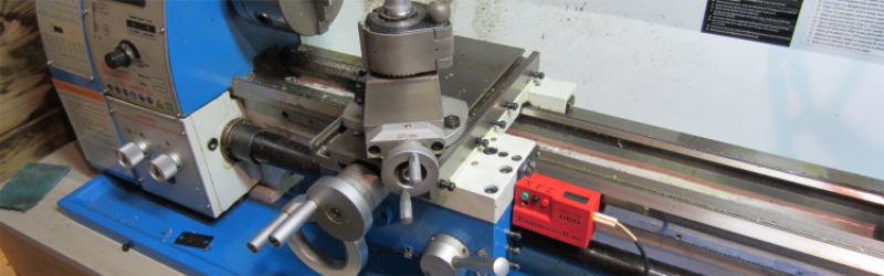
A manual lathe has dial wheels to control the feed of the main carriage and the cross slide to help take cuts on the workpiece. These feed wheels always have some backlash and require frequent resetting of the “zero”. The usual process would be to take measurements on the workpiece with either a vernier caliper or a micrometer at intervals which requires stopping the machine, adding up to increased machine time. The addition of a digital readout not only simplifies the process, but also reduces machining time substantially. Since the DRO magnetic strips are directly attached to the cross slide, the effects of backlash are mitigated.
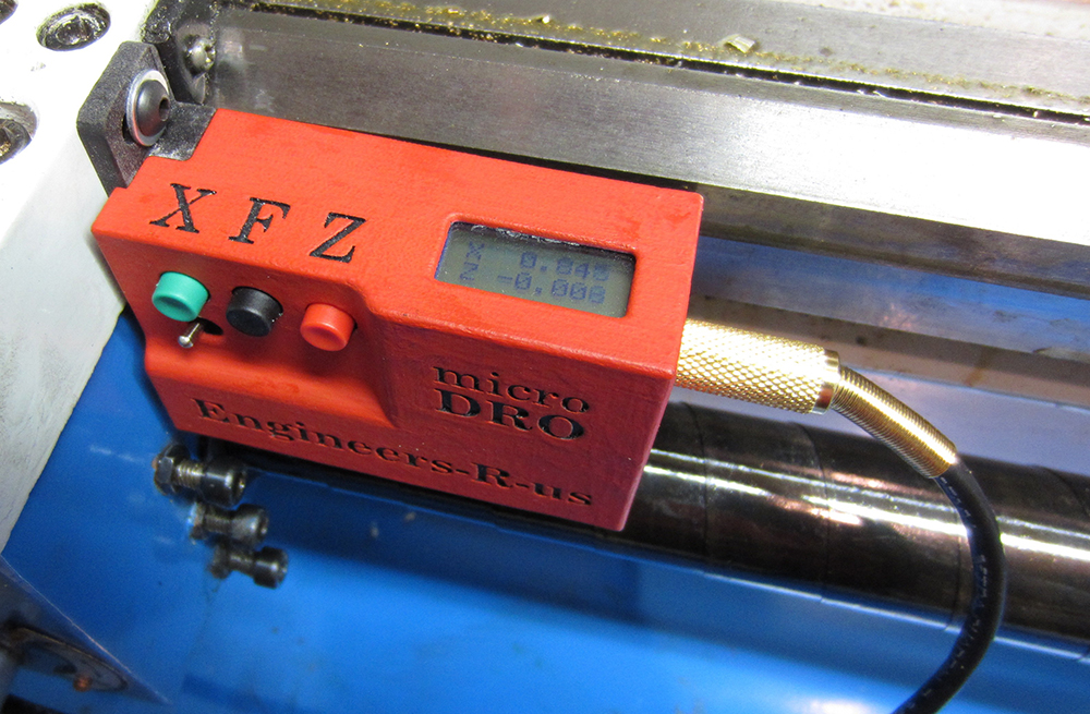 [Igor] has just such a manual lathe and built his own mini DRO unit from scratch a couple of years back. Most DRO’s have encoder strips and sensors attached to the cross slide with a larger display unit attached separately on a stalk, with wires running between the two. [Igor] kept things simple by building a unit that fit within the space constraints he had. His unit consists of just two sensor modules – each attached directly to the slide. The main unit houses a linear hall sensor, electronics, buttons, a small LCD and batteries. The second axis unit houses just the sensor with a cable connecting it to the main unit for data and power. At the heart of the system is a pair of NSE-5310 linear hall sensor encoder chips. These work in conjunction with multipole magnetic strips. The encoder provides a 12-bit output, and the magnetic strips have poles spaced 2 mm apart. This translates to a theoretical resolution of almost 0.5 microns, but of course, the machine mechanics limit the actual results. The encoder chips talk to an ATtiny2313 over the I2C bus. Three buttons and the power supply round-up the hardware. To run it off a single 1.5 V rechargeable battery, [Igor] used a boost converter to get 3.3 V. The 5 V needed for the LCD is obtained by a voltage doubler connected to a PWM output from the microcontroller and regulated by a Zener diode. The second sensor unit connects via a TRRS 3.5 mm socket.
He added a Bluetooth module as an after thought, but ran out of GPIO pins as well as program space and had to get creative to make it work. The plan was to transmit the data to an Android tablet which would work as a large, remote, wireless display. He never did use that feature though, being satisfied with the small LCD display. There’s several things that went wrong in the build, and if he were to replicate the project again, several changes and improvements would help. So if anyone plans on doing something similar, do check up [Igor]’s project logs first.


Cool solution just worried about the magnetic strips if you do any type of steel or iron (cast being the worst. Can be fun to turn but god does it make a mess) as it would stick to your strips.
The magnetic strip is behind an aluminium cover and the field is not strong enough to retain any of the chips. There hasn’t been a need to clean it in years.
What kind of buttons are those? They look fun to press.
Yuriy has an excellent DRO project that works with just about any Chinese caliper or DRO head.
http://www.yuriystoys.com/p/android-dro.html
Hey, very good link, thanks for the heads up.
Well, like mentioned in the build log, I did add a bluetooth interface to talk to Yuri’s app. It’s just that I never bother to bring the tablet.
I’m not sure you’re understanding backlash, but this is a nifty little item.
They way they describe it is pretty much the problem when working with the vernier/nonius (what is that graduated ring around the cross-slide wheels called exactly?) You need to keep backlash into account and sometimes need to reset “mid work” to 0 to keep backlash from influencing the work. (Not to mention putting your grubby mits on the ring as well as the wheel and turning it when trying to do fine adjustments. Been there, done that) It IS however a very simplified (and therefore error-prone) explanation of the problem.
The old school way to deal with backlash is to ALWAYS move the wheels in the same direction. Set your zero one time and you won’t have to set it again until the next operation/setup. A very great tool and die maker used to be the machine shop manager at UNC-Charlotte. His name was Roland Hege. Unfortunately, he passed away a few years ago. He built a small backlash demonstration tool to show new sophomore design students in the Mechanical Engineering Department. It clearly demonstrated that as long as you are always moving in the same direction you eliminate the backlash mechanically without he need to be constantly resetting your zero. Once a student used that tool to discover the effects of backlash and how to eliminate them, they were never the victim of backlash again. They understood how it worked and how to work with it to get their desired results. DROs are very nice and I loved working on machines that had them, but they aren’t the best way to get rid of the scourge that is backlash; they are simply another way.
Another issue with the DRO, if you have the backlash on the wrong side of the screw, once you apply forces (this is a bigger issue on a mill than a lathe) the table or the cross slide might move on you.
Example, if you have an extreme 0.1″ backlash on your lathe cross slide, you work the tool to the desired location as your DRO states, but you have the backlash on the wrong side of the nut. You went too far and backed it up, but didn’t go beyond the desired value and work back towards the part to ensure your backlash is taken up. Once you start pushing that tool into the work, the cross slide can slide backwards up to 0.1″ and you will see your DRO jump away from what you set it to.
I got excited about this, but the NSE-5310 is obsolete and apparently unavailable. Anyone know of any similar alternatives?
They turned it up to 11: http://ams.com/eng/Products/Magnetic-Position-Sensors/Linear-Position/AS5311
I like what you did there.
I’ve worked quite a bit with AMS chips and they are pretty sweet. Moderately easy to roll your own interface if someone hasn’t already done it for you, and the chips tend to be quite durable. I’ve seen one failure out of about 2000 chips, and that was after the end user briefly overvoltaged it.
Years ago I got one of these: http://www.shumatech.com/web/products/dro-550 and built it up for my lathe. It uses chinese calipers bolted to the lathe, reading their interface data to display position on a nice dro screen. In practice, it tends to be kind of quirky, and is pretty susceptible to noise, apparently. I think I prefer the magnetic linear encoder idea.
It is nice to have some systemic way of zeroing an axis that accounts for the tool length. It looks to me like the easiest way to do that with this setup would be to take a skim cut, measure the diameter, and then set the length based on that, and from there on out not have to keep checking, which is a big time saver. It would be cool to come up with a way of setting up a microswitch, maybe on the tailstock, so that you could set tool lengths without needing to measure after an initial cut. This would be particularly nice if you had repeatable quick-change tooling.
That’s indeed how I use it: skim cut, reset, measure, move cross slide to minus that value, reset again and then you’re good to go. One could skip the minus step and do more math in your head but it only takes a few seconds.