Over the last year, the production of homebrew electronic badges for conferences has exploded. This is badgelife — the creation of custom hardware, a trial by fire of manufacturing, and a mountain of blinky LEDs rendered in electronic conference badges. It’s the demoscene for hardware, and all the cool kids are getting into it.
At this year’s World Maker Faire in New York, there was a brand new badge given out by the folks at Consumer Reports. This badge goes far beyond simple swag, and if you take a really good look at it, you’ll see magic rendered in breadboards and wire.
The Consumer Reports breadboard badge is simple and apparently designed to introduce kids to the world of electronics like the old Radio Shack, ‘100-in-1 Electronics Projects’ kits. Unlike most of the ‘beginner badges’ we’ve seen, this isn’t a badge where you only solder a few LEDs and a battery holder to a PCB. This is a breadboard badge. This is hacking with 74-series logic. This is an impressive piece of engineering given away by Consumer Reports. No one saw this one coming. I don’t think anyone at Maker Faire realized there’s now a viable way to create breadboard badges.
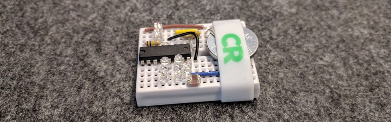
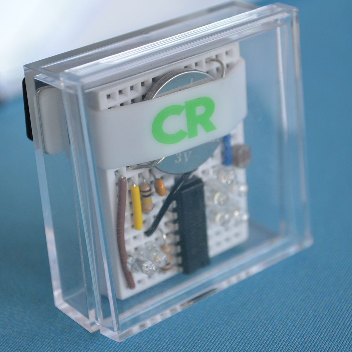 The badge given away at the Consumer Reports stall was, on the surface, extremely simple. The enclosure is a small, 2-inch-square polycarbonate case with a magnetic backing allowing the wearer to stick it to their lapel. The rest of the badge is just a small solderless breadboard, a 74HC4060 chip, seven LEDs, two resistors, a cap and a photoresistor, and a CR2032 battery. If you assemble the badge correctly — and yes, there were instructions and instructors helping the kids out — you get a blinky badge. Stick the breadboard in the enclosure, and you can wear your handiwork around the Faire.
Even though this went relatively unnoticed at Maker Faire last weekend, this is one of the most innovative pieces of wearable electronics in recent memory. Not only does it have blinky in spades, this is also a badge that can be used to teach the fundamentals of electronics. Schmitt triggers? This badge has ’em. RC oscillators? Right there, man. Want to learn about the economics of electronics? This is a working example of how to build a great badge with a minimal BOM.
A Simple Circuit Analysis
Although this circuit looks complicated with fiddly bits of wire and lots of blinkies, it’s really not. This breadboard badge is built around a single 74-series logic chip, the 74HC4060 14-stage binary counter with oscillator. The output for this chip is just a binary counter. Connect a few LEDs to the outputs of this chip, and you have a circuit that counts in binary. You could up your street cred by freerunning a CPU, but that’s beyond the scope of this badge. The input for this binary counter chip is just a clock input and a master reset pin. The binary counter advances on the falling edge of the clock input and when the master reset is low. When the master reset is high, all outputs are low.
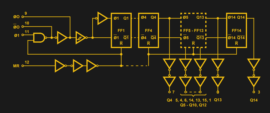
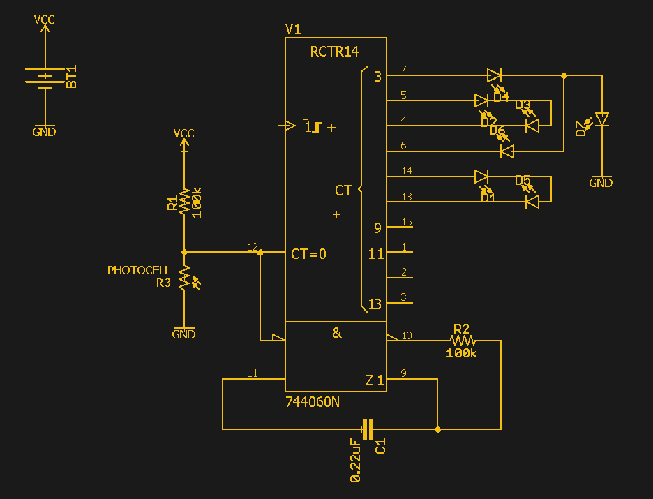
Going by the above description, it’s an easy circuit to wire up. Lots of bits on a binary counter gets you beautiful blinkies, but there’s still an open question: what generates the clock? The 74HC4060 is more than just a counter; it’s a counter with an oscillator. There are still two more outputs on the 4060 that will drive an RC circuit. Instead of a crystal, which would just drive up the cost of this kit, the 4060 can use a single capacitor and resistor to drive the clock. This is cost reduction and Real Engineering™. Add a tiny light sensor to the master reset pin, and you have a handy way to turn the circuit off — all you need to do is cover the light sensor.
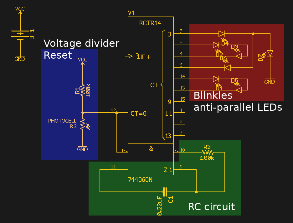
With a reasonable reconstruction of the schematic, we can get into how this badge actually works, and why this is the most educational electronic badge I’ve ever seen. Take, for instance, the reset circuit. This is just a photoresistor and a 100 kΩ resistor tied together into a voltage divider, the output of which goes directly to the master reset pin. Because the master reset is active high, you need to bring this pin up to VCC with a photocell. No problem, let’s learn how voltage dividers work. The RC circuit in this badge is a bit more obtuse unless you read the datasheet for the chip, but the basic idea is just a cap and resistor in series. Would you like to learn about logic families and how to sink and source current? That’s great because this badge is running its blinkies as anti-parallel LEDs. Since this is a binary counter, any one pair of pins will have a pin that is low and a pin that is high at the same time. Connect some LEDs to those pins anti-parallel to each other, and you have pairs of blinkies that display an interesting pattern.
From a pedagogical standpoint, this badge is amazing. Give this to a ten-year-old, include a few descriptions on how this circuit works in the instructions, and eventually, you’ll have an eleven-year-old with a better understanding of electronics than a sophomore in Circuits I. The downside of teaching electronics with this badge is that you need a teacher. The Consumer Reports booth at Maker Faire failed spectacularly in this regard — it was basically just a line of people collecting badges, and a few assembly tables at the booth. That’s sad, but there’s room for improvement.
A Sea Change For Conference Badges
In general, there are two types of conference badges. The first is extremely simple, and really not much more than a few LEDs and a battery. The official Maker Faire learn to solder skill badge falls into this category, as does the Tindie I Can Solder badge I designed for DEF CON, Maker Faire, Open Hardware Summit, and whatever other conferences we’re attending this year. These are simple, DIY badges. There’s not much to these badges because you’re giving them to people who probably can’t solder in the first place.
The second category of electronic conference badges has no limit. Here, I’m talking about AND!XOR’s Bender Badge, the SHACamp 2017 badge, software-defined radio badges, and wearable CNC machines. There’s a reason these badges come pre-assembled: no one would actually finish the build during the conference. Sure, there are exceptions like the DC Darknet and the perfboard version of this year’s SHACamp badge, but those are exceptions, not the rule.
This breadboard badge is brilliant because it fits in the middle. Most designers, when designing an obnoxiously blinky badge would lean on microcontrollers first, or, if you’re me, take the no-tech approach and toss some of those ‘flashing light RGB LEDs’ in the Tindie badge. The Consumer Reports badge is blinky rendered in logic chips using minimal circuitry for maximum effect. It’s so simple and so good, you can’t help but be impressed.


This is a badge that I can work with. Lovely.
I think there might be a few errors in your schematic.
The LEDs are described as “reverse parallel” and judging from the Breadboard Pictures they seem to be wired in this fashion.
In the schematic on the other hand they appear in a series connection (D1,D5 and D2, D3).
And the RC osc in the schematic appears to be wrong.
Cool! Also, none of the parts are custom (except the enclosure) so the overhead cost is quite low for small batch. Not using microcontrollers was a wise decision on their part. (anyone familiar with programming microcontrollers in bulk would know) Using off the shelf parts and a breadboard allows the user to add their own components and reconfigure it as they wish. It’s a shame ConsumerReports didn’t have better booth management. I would have had people teach how to make the default design, and then allow for modification to the whims of the user. One could possibly have provided a variety of components like a variety of LED’s, clocks, power supplies to customize the badges. The more technical and adventurous users could insert their personal favorite microcontrollers for added functionality! I bet CR wouldn’t mind if I borrowed parts of their idea next time somone asks me to make badges.
” I bet CR wouldn’t mind if I borrowed parts of their idea next time somone asks me to make badges.”
Well, they have been sticklers about how their name/products are used by others…
I’d just be using their general idea of using discreet logic and a breadboard in a conference badge, nothing that hasn’t been done before CR.
Discreet logic would be where you pop open the breadboard and deadbug surface mount inside it, leaving a puzzle topsides where you appear to be counting in binary with a single transistor…
+1
“Also, none of the parts are custom (except the enclosure) ”
I’m sure the enclosure is something you can get off ebay in large quantities for cheap.
+1
Ack. Wrong spot.
Pretty sure it’s just the plastic container that earrings often are sold in, missing the felt/plastic insert.
ConsumerReports !(jaw drop)!
ObPedanticComment.
When is a badge no longer a badge?
When it no longer identifies the wearer? (Identity as an individual or member of a group)
Following up on my comment,
I guess I’m thinking in the context of NAME badges, not badges of honor.
“From a pedagogical standpoint, this badge is amazing”
The badge has little to do with pedagogy. I think the term you’re looking for is “technology education”, “exploratory learning”, “constructivist/constructionist” — but not pedagogy exactly. “Here kid, figure this out” is kinda poor pedagogy.
Far out of a badge platform idea. Hopefully those who where at the event and have wishes that CR done this or done that spoke to CR to volunteer to help at the next event, and CR takes them up on the offer.
Neat badge concept. Not a fan of using CR2032 batteries in kid’s products if they’re easily accessible.
Good point, they’re behind a screwed on cover in kids stuff, but other household products…
https://consumer.healthday.com/kids-health-information-23/child-safety-news-587/flameless-candle-batteries-pose-risk-to-kids-718280.html
This is out of the box thinking with readily available hardware that has been around forever. No giant tech leap here but more importantly a leap in thought process. I really love the simplicity of the battery mount.