This Synth Is Okay

While this 3D printed synthesizer might just be okay, we’re going to say it’s better than that. Why? [oskitone] did something with a 555 timer.

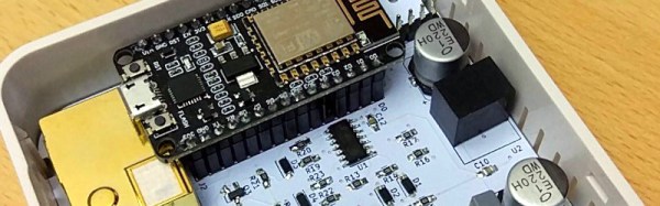
The Okay synth from [oskitone] uses a completely 3D printed enclosure. Even the keys are printed. Underneath these keys is a small PCB loaded up with tact switches and small potentiometers. This board runs to another board loaded up with a 555 timer and a CD4040 frequency divider. This, in turn, goes into an LM386 amplifier. It’s more or less the simplest synth you can make.

If this synth looks familiar, you’re right. A few months ago, [oskitone] released the Hello F0 synth, a simple wooden box with 3D printed keys, a few switches, and a single 4046 PLL oscillator. It’s the simplest synth you can build, but it is something that can be extended into a real, proper synthesizer with different waveforms, LFOs, and envelope generators.

The sound of this chip is a very hard square wave with none of the subtleties of A,S,D, or R. Turn down the octave knob and it makes a great bass synth, or turn the octave knob to the middle for some great chiptune tones. All the 3D models for this synth are available on Thingiverse, so if you’d like to print your own, have at it.

You can check out the demo of the Okay synth below.

Continue reading “This Synth Is Okay”

Over-Engineered Mailbox Flag Machined Using Under-Engineered Mini-Lathe

[Tim Nummy] used his cheap, Chinese, bench mini-lathe to make a non-terrible mailbox flag holder (YouTube video, embedded below). Tim posts videos on his channel about garage hobby projects, many of which are built using his mini-lathe, often based on suggestions from his followers. One such suggestion was to do something about his terrible mailbox flag – we’re guessing he receives a lot of old-school fan mail.

He starts off by planning the build around 1 ¼ inch aluminum bar stock, a 688 bearing, three neodymium magnets and some screws. The rest of it is a “think and plan as you go along” project, but essentially, the new holder is in three pieces. An inner piece goes inside the mail box and holds the assembly to the mail box. The middle piece holds the two magnets which act as end-stops or limits for the flags raised and lowered positions. The final, outer piece holds the flag itself, and the bearing which allows it to rotate freely.

This part also has the third magnet embedded in it to work with the other two magnets for the limits. The use of magnets is cool, but a ball catch with two detents would have worked just as well. It’s a great simple project to follow for those who want to wet their feet on lathe work. [Tim] has also posted links to all of the tools and equipment seen in the video, so check that out if anything catches your fancy.

But workshop veterans will almost certainly cringe at several places along the video. The main one that caught our eye is obviously the shaky lathe itself. It could do with a heavier workbench, proper leveling, foundation bolts or anti-vibration mounts. And from the looks of it, the tail stock isn’t any rock steady too. Although the lathe is variable speed, the chuck rpm is set too high for aluminum, and the lack of cutting fluid makes it even more troublesome. Using oil, or even some cutting fluid, while tapping would have been wise too.

We’re not sure if it’s the shaky foundation or poor feed control, but the step cut for mounting the bearing is over-sized by a whole lot more and requires a big goop of retaining compound to glue the bearing in place. But the end result works quite well, including the magnetic catches – a complex solution for a simple problem.

We’re sure our keen-eyed readers will likely spot some more issues in [Tim]’s methods, so go at it in the comments below, but please make sure to rein in the snark and keep your feedback positive.

Continue reading “Over-Engineered Mailbox Flag Machined Using Under-Engineered Mini-Lathe”

Impressive Electric Quad Bike

[EV4] is a small Polish company that makes electric vehicles, like this rather cool electric quad It’s an impressive build, including two 1 kW motors and a tilting turning system that makes it more maneuverable than most quad bikes. It has big, wide tires, a raised battery and longitudinal arms that mean it can climb over obstacles. That all makes it great for off-road use, and it’s just 60 cm (just under 24 inches) wide, which is much smaller than most quad bikes. It also has a top speed of 35 km/h, which would make it somewhat illegal to use on the public roads in many places. As someone who can’t ride a two-wheel bike because of a lousy sense of balance, I’d love to build something like this. Has anyone got plans for something similar?

Continue reading “Impressive Electric Quad Bike”

Drag Your Office Aircon Into The 21st Century With Wi-Fi Control

We’ll all have worked in offices that have air-conditioning, but a little too much of it. It’s wonderful on a baking-hot day to walk into the blessèd cool of an air-conditioned office, but after an hour or two of the icy blast you’re shivering away in your summer clothing and you skin has dried out to a crisp. Meanwhile on the other side of the building [Ted] from Marketing has cranked up the whole system to its extreme because he’s got a high metabolism and an office in the full force of the midday sun.

Wouldn’t it be nice if individual air-conditioning units could be easily controlled. To that end, [Maya Posch] has made a rather nicely designed board that takes a NodeMCU board with its ESP8266 processor, and uses four of its outputs as PWM to produce 0-10 volt analogue outputs via filters and op-amps to control individual units. In addition there is an onboard CO2 sensor and a temperature sensor, with provision for an external temperature sensor. The whole fits very neatly into a standard electrical outlet enclosure.

Software wise, the system uses the Sming framework providing an MQTT  communication with a backend server that allows the users to control their aircon experience. This is very much a work in progress, so the software has yet to be put up. (Hint, [Maya], hint!) The whole project though is an extremely tidy build, in fact a thing of beauty to a standard you’d expect from a high-quality commercial product. It’s this that tipped the balance into our featuring it before the software is released, it’s one to keep an eye on, because quality like this doesn’t come every day.

This isn’t the first aircon control we’ve brought you, take a look at this one controlled through Slack.

Hackaday Prize Entry: Telepresence With The Black Mirror Project

The future is VR, or at least that’s what it was two years ago. Until then, there’s still plenty of time to experiment with virtual worlds, the Metaverse, and other high-concept sci-fi tropes from the 80s and 90s. Interactive telepresence is what the Black Mirror Project is all about. Their plan is to create interactive software based on JanusVR platform for creating immersive VR experiences.

The Black Mirror project makes use of the glTF runtime 3D asset delivery to create an environment ranging from simple telepresence to the mind-bending realities the team unabashedly compares to [Neal Stephenson]’s Metaverse.

For their hardware implementation, the team is looking at UDOO X86 single-board computers, with SSDs for data storage as well as a bevy of sensors — gesture, light, accelerometer, magnetometer — supplying the computer with data. There’s an Intel RealSense camera in the build, and the display is unlike any other VR setup we’ve seen before. It’s a tensor display with multiple projection planes and variable backlighting that has a greater depth of field and wider field of view than almost any other display.

Teaching Electronics With A Breadboard Badge

Over the last year, the production of homebrew electronic badges for conferences has exploded. This is badgelife — the creation of custom hardware, a trial by fire of manufacturing, and a mountain of blinky LEDs rendered in electronic conference badges. It’s the demoscene for hardware, and all the cool kids are getting into it.

At this year’s World Maker Faire in New York, there was a brand new badge given out by the folks at Consumer Reports. This badge goes far beyond simple swag, and if you take a really good look at it, you’ll see magic rendered in breadboards and wire.

The Consumer Reports breadboard badge is simple and apparently designed to introduce kids to the world of electronics like the old Radio Shack, ‘100-in-1 Electronics Projects’ kits. Unlike most of the ‘beginner badges’ we’ve seen, this isn’t a badge where you only solder a few LEDs and a battery holder to a PCB. This is a breadboard badge. This is hacking with 74-series logic. This is an impressive piece of engineering given away by Consumer Reports. No one saw this one coming. I don’t think anyone at Maker Faire realized there’s now a viable way to create breadboard badges.

Continue reading “Teaching Electronics With A Breadboard Badge”

World’s Largest Telescope Stopped By LED

Earlier this year a simple indicator LED brought the Keck 1 telescope, a 370 tons mass, to a halting stop. How exactly did an LED do this? Simple: it did nothing.

As it so happens, [Andrew Cooper] was just about the leave the summit of Mauna Kea (in Hawaii) when his radio instructed him otherwise: there was an issue. Upon returning, [Andrew] was met by a room of scientists and summit supervisors. “Yeah, this was not good, why are they all looking at me? Oh, h%#*!” The rotor wasn’t moving the telescope, and “no rotator equals no science data.” After being briefed on the problem, [Andrew] got to work. Was it a mechanical issue? No: manual mode worked quite fine, also indicating that the amplifiers and limit switches are functional as well.

Jumping from chip to chip, [Andrew] came across an odd voltage: 9.36V. In the CMOS [Andrew] was investigating, this voltage should have High (15V) or Low (0v) and nowhere in between. Judging by the 9.36V [Andrew] decided to replace the driving IC. One DS3632 later, nothing had changed. Well, maybe is one of the loads pulling the line low? With only two choices, [Andrew] eliminated that possibility quickly. Likely feeling as if he was running out of proverbial rope, [Andrew] remembered something important: “the DS3236 driving this circuit is an open collector output, it needs a pull-up to go high.”

Reviewing the schematic, [Andrew] identified the DS3236’s pull-up: an LED and its current limiting resistor. While the carbon composition resistor was “armageddon proof,” [Andrew] was suspicious of the LED. “Nick, can you get me a 5k resistor from the lab?” Hold the resistor on the pins of the chip and the amplifiers immediately enabled.

[Andrew] summarizes things quite well: “yes… One of the world’s largest telescopes, 370 tons of steel and glass, was brought to a halt because of a bad indicator LED”. It stopped things by doing nothing, or rather, by not turning on.

We love it when we get troubleshooting stories, and if you share our interest in problem-solving, check out this broken power supply troubleshooting or learn what could go wrong with I2C.

Edit: Keck 1 is one of the largest optical telescopes in the world. Thanks to [Josh] for noticing our error.