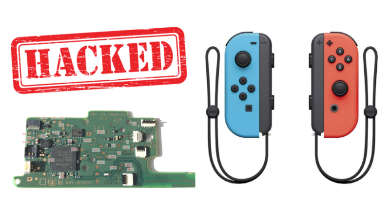
The Switch is Nintendo’s latest effort in the console world. One of its unique features is the Joy-Cons, a pair of controllers that can either attach directly to the console’s screen or be removed and used individually. But how do they work? [dekuNukem] decided to find out.
The reverse engineering efforts begin with disassembly. Surprisingly, there is no silkscreen present on the board to highlight test points or part numbers. This is likely to conflate intended to stymie community efforts to work with the hardware, as different teams may create their own designations for components. Conversely, the chips inside still have their identifying markings present, which does ease identification somewhat.
There are some interesting choices made – the majority of the buttons are scanned in a matrix configuration by the on-board microcontroller, making it harder to spoof button presses. The controllers communicate over Bluetooth, switching to a physical serial connection when attached directly to the screen. This runs at a blistering 3,125,000 BPS after the initial handshake is completed.
Overall it’s a fairly comprehensive reverse engineering effort, and [dekuNukem] has provided excellent detail in the writeup for anyone else looking to get involved. There’s still some work left to do, like investigating the rumble messages, but it’s an excellent start and very comprehensive.
Perhaps you’re more interested in older Nintendo hardware? Check out this comprehensive effort to figure out NES console-to-cartridge security methods.


>They used the keypad scanner built-in inside the BCM20734 with 128KHz clock for reading the buttons. That means it would be extremely hard to spoof button presses
extremely hard as in use $0.1 transistor?
I was thinking the same. Just a simple mosfet, using 3.3v in its gate should suffice.
I’m a very amateur electronics hobbiest. Could you explain to me how a mosfet would help in this situation? I’d love to do a project to be able to trigger button presses on a joycon, but don’t have the full understanding of this specific part about the keypad scanner thing and whatnot.
If the sense voltage alternates across the contacts, which is common, in my experience, a simple transistor or mosfet won’t do it.
Last time I had to simulate button presses on a key matrix that did this, I had to use magnetic relays to actually make the contact, because every solid state relay I could find at the time conducted in one direction when “open”. It was a noisy mess.
“This is likely to conflate community efforts to work with the hardware,”
http://www.quirkbooks.com/sites/default/files/u1125/inigo.jpg
confound
defeat (a plan, aim, or hope).
“we will confound these tactics by the pressure groups”
You’re welcome
Ohhhh, I was thinking it was a typo of conflatulate, as in make farty. ;-)
An awesome hacking effort, and y’all are talking words?
(Fixed. Thanks.)
Conflate
1.To combine two things into one, ideas, texts. “You shouldn’t conflate the fireman saving you with a desire for a romantic relationship”
Though that would be a clearer example if worded “the fireman’s act of saving you..”
Parallelism.
As opposed to “flatulate”.
Oh hey!
If anyone wants to crack open their own Joy-Con (non-invasively) I built a Unity library for Mac and PC which can read and visualize IMU data and send waveforms to the HD Rumble motors. Makes a great 6axis VR controller / antitheft device / interactive art installation component / baby monitor / couple’s vibrator / you name it.
https://gbatemp.net/threads/joy-con-unity-library.486629/
https://hackaday.io/project/27986-joyconlib
https://github.com/Looking-Glass/JoyconLib
Pull requests welcome!
“This is likely to conflate community efforts to work with the hardware,”
I’ve seen quite some boards without silk screen. Maybe it’s a cost saving effort?
It was however a quite dastardly plan back in 1998 before the ubiquity of digital cameras when you couldn’t post a pic with a red circle around the component saying “That one”
Kinda like that bit in the movie “Timeline” when they tried to imply it was a dastardly trick for the archers NOT to light their arrows on fire at night so they could see incoming.
Oh! How dafterly!
I typically work on controller with silk screen, but redacted chips:
http://www.wolftronix.com/umoc340_15/images/IMG_0188.jpg
I would prefer the missing silk screen. ;)
Ha, they even try to hide the EPROM chips make, how silly.
As an EE designer for mass-production products: almost certainly a cost-saving measure to remove silkscreen. Saves a few pennies on every board to avoid that step.
But they put a fancy logo on it. and lots of text.
I think it’s just because the pick and place machines making them don’t need any of the part indicators.
Sorry but yes, and no. That isn’t silkscreen which would be yet another layer. They just reused the solder mask layer which is a total freebie as all your SMT parts need it anyways.
If that is true (hard to tell for sure from the picture) they could have also used that to indicate the parts.
I recently played this handheld and was shocked by the build-quality of the joy cons. The plastic creaks and you can insert the joycons the wrong way around into the metal rails (hey could’ve been plastic!) of the glorified android tablet. These compromises save more money than a silkscreen. Which brings us here: this is not a device intended to be repaired or constructed and QA’ed by humans but (pick and place) machines, so simply no need for silkscreen (and they didn’t design it in fritzing :p).
It’s fairly comprehensive effort. There’s some left to do, but it’s a start and very comprehensive.
That seems repetitive.
You could say it’s comprehensiveness is comprehensive in it’s comprehensive scope.
How to hack the controller wake up switch console?