Rotary encoders are critical to many applications, even at the hobbyist level. While considering his own rotary encoding needs for upcoming projects, it occurred to [Jan Mrázek] to try making his own DIY capacitive rotary encoder. If successful, such an encoder could be cheap and very fast; it could also in part be made directly on a PCB.
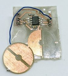
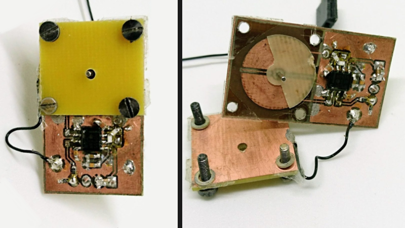
The encoder design [Jan] settled on was to make a simple adjustable plate capacitor using PCB elements with transparent tape as the dielectric material. This was used as the timing element for a 555 timer in astable mode. A 555 in this configuration therefore generates a square wave that changes in proportion to how much the plates in the simple capacitor overlap. Turn the plate, and the square wave’s period changes in response. Response time would be fast, and a 555 and some PCB space is certainly cheap materials-wise.
The first prototype gave positive results but had a lot of problems, including noise and possibly a sensitivity to temperature and humidity. The second attempt refined the design and had much better results, with an ESP32 reliably reading 140 discrete positions at a rate of 100 kHz. It seems that there is a tradeoff between resolution and speed; lowering the rate allows more positions to be reliably detected. There are still issues, but ultimately [Jan] feels that high-speed capacitive encoders requiring little more than some PCB real estate and some 555s are probably feasible.
This project is a reminder that FR4 (whether copper-clad, etched, or blank) shows up in clever applications: copper tape and blank FR4 can be used to quickly prototype RF filters, PocketNC built an entire small CNC tool around FR4, and our own [Voja] wrote a full guide on making beautiful enclosures from FR4.


Kind of like the linear sensor in some calipers.
Some use a wibbly, [ not wobbly timey wimy, that’s screwdrivers] trace fed with rf and a pickup coil. A bit like a linear version of a usb sketch pad and pen.
I remember building a variable capacitor out of old sauspans for a crystal set many, many years ago. Granted I tend to buy them for simplicity and costs sake unless it’s something aesthetic or needs to cope with loads of high voltage or similar custom application.
Very cool.
Oh wow. It’s even done with a 555 timer.
Now for a quadrature version?
The way to null out differences in humidity and temperature etc. is to compare between two capacitances, not just use a single overlapping plate pair.
Feeding the same high-frequency signal to both capacitors causes a different phase shift depending on the capacitance value, so the phases of the outgoing signals will be different, and whatever mutual capacitance changes apply the same to both so the common mode error is removed.
So, a 555 for a signal generator and a pair of comparators to clean the signal out, then just subtract the signals from each other. When both phases are the same, zero output. If one leads the other, positive or negative spikes start to appear, the width of which are proportional to the angle.
Yes, this is a solution – however I wasn’t able to build a circuit similar to Mr. Chans (http://elm-chan.org/works/vlp/report_e.html) – it was just to noisy. That’s why I tried to go with the “das a bug in the boardre wigital” way – to measure frequency a do similar thing in software. However the design and the two 555 timer interfere with each other.
That circuit doesn’t eliminate the mechanical noise in the system, because it relies on shunting the current to ground and measuring how much current is shunted, so when the plates vibrate axially you get the same vibration in the output.
The phase comparison doesn’t care about the exact capacitance of the plates, as long as both change the same amount, so both phases advance or retard the same amount.
Also, why two 555? You only need one.
no 556
More precisely, positive AND negative spikes start to appear, but the order relative to the original signal changes depending on which way the sensor spins.
Just like the home made one at the back of Mr Chans Galvo http://elm-chan.org/works/vlp/report_e.html
FDC2212
Thanks for sharing such a clever solution.
@Honza Mrázek:
I’m pretty sure your proposed solution for the continuous rotation problem is faulty.
[img]http://blog.honzamrazek.cz/wp-content/uploads/2017/07/pattern.png[/img]
If I’m not mistaken there are at least 4 positions where turning the dielectric disk up to +/- 1/6*pi wont register with the circuitry.
Explaination/example:
If one turns the dielectric disk so that A1, B1 and 2/3rds of A2 are covered by the dielectric, then electrode B2 is completely uncovered.
Now while turning to cover A2 completely and uncovering 1/3 of A1 the electrical characteristics wont change at all.
You wont know if the dial is turned at all!
I think there is no solution to this problem with just one uniform dielectric disk and logically two different electrodes (not counting the common ground electrode).
You either need three different electrodes or an dielectric disk with two different permittivities (three different permittivities in total).