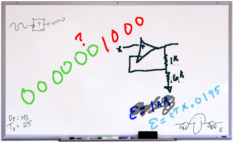
Marketing guys love bigger numbers. Bigger is better, right? After all, Subway called it a “footlong” not an 11-incher. So when it comes to analog to digital (A/D) conversion, more bits are better, right? Well, that depends. It is easy to understand that an A/D will have a low and high measurement and the low will be zero counts and the high will result in the maximum count for the number of bits. That is, an 8-bit device will top out at 255, a 10-bit at 1023, and so on.
The question is: are those bits meaningful? The answer depends on a few factors. Like most components we deal with, our ideal model isn’t reality, but maybe it is close enough.
Fundamentals
The concept of an A/D converter is pretty simple. Take an analog signal in some range of voltages and convert it to a digital number. Assuming we are talking about a linear conversion, which is usually, but not always, the case, then the range of the number will correspond to the range of the voltage.
In other words, if the A/D can produce a count of 0 to 100 and the voltage ranges from 0 to 1 V, then a count of 100 is 1 V, 50 is 0.50 V and 12 is 0.12 V. In real life, though, most will use a count that is a power of two to maximize their resolution. That is, and 8-bit A/D will range from 0 to 255, and 10-bit from 0 to 1023, and so on.
The voltage range can — in theory — be anything. Sometimes it will be 0 V to 5 V or maybe -2.5 V to 2.5 V. Sometimes the reference will be a voltage that divides exactly by the count like 4.096 V, for example.
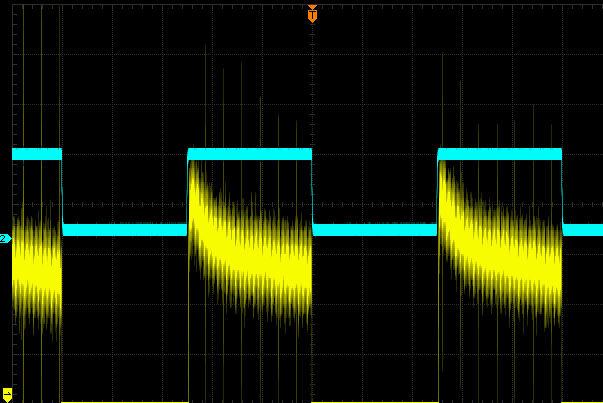 Let’s suppose you have a 10-bit A/D with a range of 0 V to 4.096 V. Each bit will be worth 4 mV — in theory, at least. However, suppose your circuit is subject to +/-24 mV of noise. Then even if the A/D were perfect, you really can’t trust the last two bits. That seems obvious, so keep your system noise low. The converter can only convert what it sees, it isn’t a mind reader. If you AC couple a scope and zoom in on a nice clean square wave, you’ll see plenty of up and down. In fact, the image to the right shows a blue square wave and the same square wave’s top (in yellow) amplified. The A/D converter will dutiful record these little irregularities. The question becomes: where is this noise coming from. Obviously, noise that is in your system is out of the control of the A/D converter, but that’s only part of the story.
The Blame Game
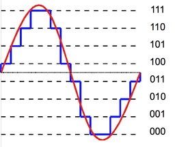 The problem is that your A/D isn’t perfect to start with. It should be plain that even if it were perfect, the A/D can’t split that least significant bit. That is, given the above example, measuring 1.000 V, 1.001 V, and 1.002 V isn’t likely to give you a different value even if there is no inherent system noise. This is quantization noise and appears to be — in this case a +/-2m V noise on the input, since the quantization level is 4 mV. You can see this graphically, to the left.
I’ll skip the math, but you can determine that for a signal greater than 1 bit value (4 mV, in this case) the noise will be 1.76 dB. You can use this to arrive at an ideal signal to noise ratio (SNR) for a given word length. That formula works out to 6.02 times B (where B is the number of bits). Remember, that’s ideal — you won’t even get that good. Our 10-bit A/D, then, can’t do better than 60.2 dB. If you need a refresher on dB, by the way, we did that already.
Consider this: if SNR of an ideal A/D is 6.02 dB times B then it stands to reason if we have a real A/D with a measured SNR, we could figure out how many “ideal” bits it has by rearranging the math. This is the ENOB of “effective number of bits” you may see on a data sheet. To get the ENOB, you subtract 1.76 from the measured SNR and then divide by 6.02. By the way, you usually hear ENOB pronounced “E-Knob.”
Let’s say our 10 bit A/D has a 51.76 dB measured SNR. Then 50/6.02 = 8.3. Our 10-bit device is performing only a little better than an ideal A/D with 8-bits of resolution.
Keep in mind that this noise is only due to the steps in the A/D. There are other sources of noise in a real A/D, including noise from components like resistors and other sources.
There are other even more subtle sources of errors. Nonlinearity in the conversion is one example. Essentially, the voltage change that corresponds to one bit may differ across the measured range. While the nominal value of a count in our example is 4 mV, it might be 3.95 mV on one end and 4.02 mV on the other end.
Another issue is clock jitter. You always sample at some rate. That is, you might take 10,000 samples per second or 1 million, but there is always some discrete time step. At low input frequencies, that sample clock can be pretty sloppy. As frequency goes up, though, any jitter in the clock can cause an error higher than the quantization noise.
Clock jitter gets even more of a problem as the count size goes up, since the resolution is better, and thus the quantization noise is less. For example, for an 8-bit converter, a 1 kHz sinewave won’t gain any error unless the jitter is more than 1.24 microseconds. A 12-bit converter needs to control jitter to less than 77.7 nanoseconds for the same input. Of course, as the signal frequency rises, the maximum allowable jitter goes down. That 8-bit converter would need to keep jitter to less than 12.4 picoseconds at 100 MHz, or 0.78 picoseconds for the 12-bit device.
Although the video below talks about jitter in PLL systems, the background information on what jitter looks like is generally useful. If you’ve ever wondered the difference between jitter and wander, you’ll want to check out this video.
Dithering
Noise is bad, right? Not always. It turns out when processing audio or images, there is an unfortunate side effect of quantization. Consider a simple example. Suppose you have a converter where each count is 0.1 V. You are measuring a repeated signal that has 0.09 V, 0.10 V, 0.11 V, and so on. You are only going to read 0.1 V and 0.2 V in this range, and exactly how you choose to round will determine which readings get classified as 0.1 and which as 0.2. If the signal is audio or even an image and if you reconstruct the signal, your brain will pick out the pattern. For example, in an image, you might see a stripe of one color that isn’t in the original.
Audio engineers do the same process if they are going to reduce sample sizes for the same reason. The video below covers that and the same ideas apply. The “rounding” in our case isn’t in the reduction of the sample size, but in the sampling one point and letting it represent a range of the signal.
An answer to this is to inject white noise of plus or minus a half bit’s worth into the input stream. In the above example, you’d inject +/- 0.05 V. This has the effect of randomly causing some values to round up and some to round down with no discernable pattern. Averaging over these values can actually increase resolution.
Often the noise can appear outside the frequency range the rest of the system is looking for, so it is easy to filter out. You can read more about that technique and also many other details about noise sources in A/Ds in this good and short article from Analog. If you want to hear more about ENOB, TI has the video below.
Take What You Know…
All these bit calculations are interesting, but an even more interesting topic for another day is how these converters work (and the reverse, too, of course). My old math teacher used to say “Take what you know and use it to find out what you don’t know.” I always think of that saying when I’m dealing with any sort of converter. Our computers are good at counting and counting time. They are bad at measuring voltages, currents, temperatures, and other real-world quantities. So most converters somehow convert those quantities into either counts or time. For example, a successive approximation converter will convert a count to a voltage and compare it to the unknown voltage. An unknown resistance might form a time delay with a capacitor and the computer can measure that time.
I’d talk more about analog to digital converter architectures, but [Bil Herd] already covered that nicely. If you are interested, it doesn’t cover every possible type of converter, but it does explain the ones you are most likely to see.
Just like you track significant digits in calculations or take into account real-world component inaccuracies in other designs, building — or even using — an effective analog converter requires you to understand the math well enough to not trust or even convert bits that don’t mean anything.
Photo credits:
Quantization error sine wave – [Hyacinth] CC BY SA 3.0.


Not every bit is worth 4mV in your example. The first is 1mV, the second 2mV and so on.
Otherwise, great article. Thanks!
Let’s suppose you have a 10-bit A/D with a range of 0 V to 4.096 V. Each bit will be worth 4 mV —
4.096/1024 = .004
each step or LSB is worth 4mV
Only the least significant bit is worth 4mV. Each successive bit is worth double that, otherwise the 10-bit ADC would only provide a range of 40mV :)
Did you perhaps mean each “step” is worth 4mV?
It’s interesting that this distinction is being made; in CAN communication (specifically J1939) it’s normal to refer to the resolution of a value as being “4mV per bit”.
I think you confused him by choosing 4.096 for the range. Someone who does this a lot can easily see that number and jump to 12 bits.
On another item, why do you choose to specify all the noise as +/- some V instead of an amplitude?
Also in “Let’s say our 10 bit A/D has a 51.76 dB measured SNR. Then 50/6.02 = 8.3. Our 10-bit device is performing only a little better than an ideal A/D with 8-bits of resolution.” You might say an ideal 8 bit A/D reading a noise free signal. Would that be right?
4096 setps are for 12 bit ADC, not 10 bit.
“That is, and 8-bit A/D will range from 0 to 255, and 10-bit from 0 to 4095, and so on.”
Please correct this. 10-bit from 0 to 1023.
(First time it is OK, the second time it’s wrong.)
Dang it. I originally wrote it as 12 bit and then when I made the example 10 bit I didn’t fix this. Will fix it now. Thanks for the catch.
Re dithering, I’ve found that a couple of popular microprocessor a/d’s are actually a little better than spec if there’s a little noise in the system, you oversample, and average the samples back down to the real sample rate you wanted. One example is the Arduino Uno – I regularly get a few extra bits out of that one with this trick – and they really are good, as tested with a precision dc source. PICs often can give you about 1 extra bit as well. Both have better internal linearity than is required to meet their spec, which is why this works.
What I do is sample 4 times per actual output sample, and sum the samples. While in theory, if everything was perfect, you’d get 2 extra bits this way, in practice you get about 1 more good one. In a case of some data acq I do here, the output rate is 10hz per a/d channel – so oversampling well in excess of that is a reasonable thing to do in a uP. If you don’t do this, you’ll normally lose even the bits it theoretically has due to noise flipping the LSB (at least) around. Interesting things happen if there’s noise that is some fairly simple multiple (or close) to your sample rate. If you were sampling at say 6 hz, you might catch 60hz noise at always the same phase, which then looks like a DC offset….if they aren’t exact multiples, you see a beat note in your data.
That’s called “processing gain” – and its your DSP best friend.
Yup, in theory it improves with the square root of the amount of oversampling. 4 samples: twice better. 16: four times better.
Downsampling by four gives you one extra bit, and downsampling by 16 gives you 2 bits.
Which means your 8-bit becomes a 10-bit ADC.
If Xilinx ever release those FPGA’s with a built-in 4 GSPS ADC, you could downsample to 250MSPS and get 2 more bits resolution. Depending on the bandwidth of the signal you are chasing, you can repeat this – by the time you get down to AM radio (about 9 KHz) you have added about 9 bits of resolution to the original ADC.
Unlike your experience with the UNO, I found that I didn’t have enough noise in the 328p to over-sample on a 3.3v Pro-mini board. So I did some experimenting with different methods to generate that dithering noise:
https://edwardmallon.wordpress.com/2017/02/27/enhancing-arduinos-adc-resolution-by-dithering-oversampling/
Turns out you can do a reasonably good job by simply toggling a digital pin with a resistor on it while you do the ADC readings – though synchrony generates some small offsets that need to be taken care of in calibration.
there is the same issue with photography: Woah! your sensor has a ton of pixels. Hum, is your optical package able to resolve less than 1px detail? the answer is generally no in the modern world.
In sensor DSP they now “dither” the position of the detector to get sub-pixel resolutions. It is a hot topic at the moment.
Can’t you just run 12 clocks (random number) and force an average to get less jitter? Or use some other electronic version of what watches use to prevent non-linearity?
BTW it’s funny how there is noise and bad sound on a video talking about signal quality made by a big electronics company. Makes you wonder if they know what they are doing.
Am I the only one who would like to see a little more math in these pieces?
For example, the part about sample frequency jitter noise (or error – I don’t know what kind of noise it is). I found myself thinking the error will be related directly to the rate of change of the signal, the (delta V/delta t). The dv/dt of a sine is a cosine. The max value of a sine or cosine is 1, so this is where the the signal crosses the t axis. The dV/dt=1 makes it almost trivial to calculate dV in one sample period and in the fraction of a period that represents jitter.
Applied to a 1kHz signal, it should be pretty easy to show how much jitter produces errors greater than 1bit, 2bits, etc. Then you can use this info when choosing sample rates.
We don’t need to get into types of noise and all that, but enough math to generate a rule of thumb maybe?
A similar trick was used in consumer keyboards for years though backwards.
I’m new to this, so I’m a little confused on the opening statement. If each step is 4mV, and you have noise of +/- 24mV won’t that make you unable to trust the last 3 bits not 2?
I would like to mention that quantization error is not linear over the range of the adc. One bit of error at the bottom is 4mV in this example, so for the range 4mV to 8mV you could have error of 100% (depending on where your threshold to flip a bit is). Looking at the upper range an error of one bit at 4095 mV is about 0.1%. So unacceptable error at the low end, and wasted bits at the upper end, with error proportional to 1/V. It turns out the the cure is to put your signal thought a log-amp (d(log(x))/dx is 1/x after all…). Then you get error in dB/bit, which keeps it proportionally constant over the entire range. Then just exponentiate in software.
I think that is why the spec linearity, monotonic, differential error and integral error relative to the full range.
You lost me. In lame man term please
Sure. Linearity means if you add the output you get for an input of 2 and an input of 3, you get the same answer as you do when the input is 5.
Monotonic means each input produces only one output and that codes (output values) come one after the other in counting order.
Differential error is the error you see if you check steps against the previous or next code versus a precise input voltage that is varied. In a perfect converter, the output steps change every time the input changes by exactly the same amount.
Integral error is the error over large ranges of outputs. It can be the sum of all the differential errors. I think best described as the deviation from the ideal value and usually measured from the center of a step.
There is also often a guarantee of “no missing codes” which means as you sweep through the input range, say with a voltage ramp, the converter does no skip any values. For example, the output changing from 3 to 4 then sticking on 4 until the input makes it move to 6.
These are all spec’d by ADC manufacturers along with input impedance and frequency and often many other parameters. I have found sometimes I just can’t get the info, like for the ADC on an ESP32, when they are in microprocessors. I think Espressif doesn’t have the test equipment or experience to produce the info. If I recall, others like the high speed 12 bit ADC’s on the STM32F4 are fully specified.
Now for a little practical lab, your digital to analog converter in the computer you are looking at. Most people leave the volume slider on their computer at some middle position so they can turn it up when wanting it loud or for the frustrating YouTube video with sound at -10 or more dB.
In standard audio practice the level at all points in the mixing chain is near full with no clipping and expected headroom preserved. Only the final power amp gain is the one to adjust final loudness as actual sound.
In digital audio there is the need to use all 16 bits to full advantage, and there is no headroom at all. Thus the final amplifier gain is the only way to adjust overall loudness. Simply put, run that volume slider on the computer up to 100% of gain (not over) and get your volume knob within reach. Those with their sliders at half staff are just getting something like 8 to 12 bits worth or less at normal all the time listening levels.