When you acquired your first oscilloscope, what were the first waveforms you had a look at with it? The calibration output, and maybe your signal generator. Then if you are like me, you probably went hunting round your bench to find a more interesting waveform or two. In my case that led me to a TV tuner and IF strip, and my first glimpse of a video signal.
An analogue video signal may be something that is a little less ubiquitous in these days of LCD screens and HDMI connectors, but it remains a fascinating subject and one whose intricacies are still worthwhile knowing. Perhaps your desktop computer no longer drives a composite monitor, but a video signal is still a handy way to add a display to many low-powered microcontroller boards. When you see Arduinos and ESP8266s producing colour composite video on hardware never intended for the purpose you may begin to understand why an in-depth knowledge of a video waveform can be useful to have.
The purpose of a video signal is to both convey the picture information in the form of luminiance and chrominance (light & dark, and colour), and all the information required to keep the display in complete synchronisation with the source. It must do this with accurate and consistent timing, and because it is a technology with roots in the early 20th century all the information it contains must be retrievable with the consumer electronic components of that time.
We’ll now take a look at the waveform and in particular its timing in detail, and try to convey some of its ways. You will be aware that there are different TV systems such as PAL and NTSC which each have their own tightly-defined timings, however for most of this article we will be treating all systems as more-or-less identical because they work in a sufficiently similar manner.
Get That Syncing Feeling
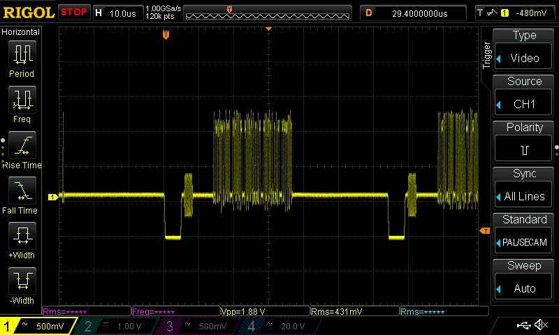
Looking at the synchronisation element of a composite video signal, there are two different components that are essential to keeping the display on the same timing as the source. There is a short line sync pulse at the start of each individual picture line, and a longer frame sync pulse at the start of each frame. The line sync pulses are a short period of zero volts that fills the time between the picture line.
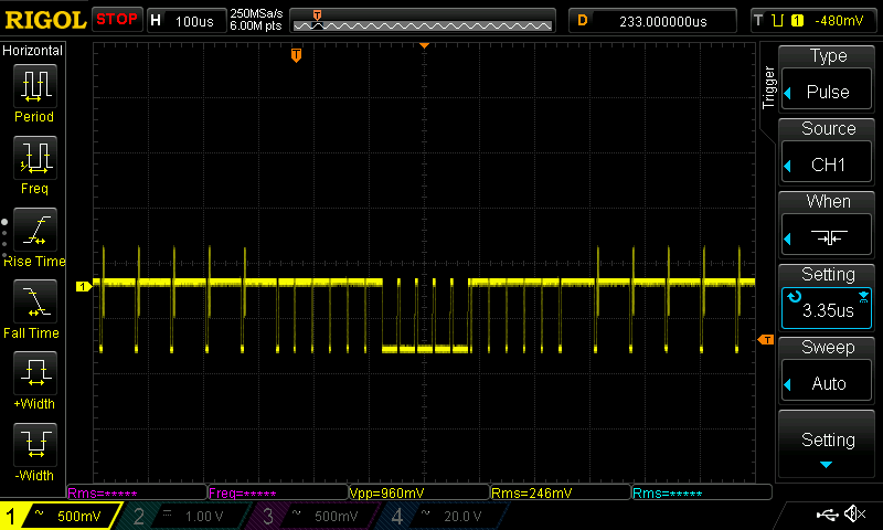
In the close-up of a single picture line above there are two line sync pulses, you can see them as the two rectangular pulses that protrude the lowest. Meanwhile in the close-up of a frame sync period to the right you can see the frame sync pulse as a period of several lines during which the entire signal is pulled low. Unexpectedly though it also contains inverted line pulses. This is because on an older CRT the line oscillator would still have to be able to detect them to stay in sync. This frame sync pulse is surrounded by a few empty lines during which a CRT display would turn off its electron gun while the beam traversed the screen from bottom right to top left. This is referred to as the frame blanking period, and is the place in which data services such as teletext and closed-captioning can be concealed. In the spirit of electronic television’s origins in the early 20th century, both types of sync pulses are designed to be extracted using simple RC filters.
Know Your Porches
The area around the line sync pulse is particularly interesting, because it contains the most obvious hint on an oscilloscope screen that a composite video signal is carrying colour information. It also has a terminology all of its own, which is both mildly amusing and useful to know when conversing on the subject.
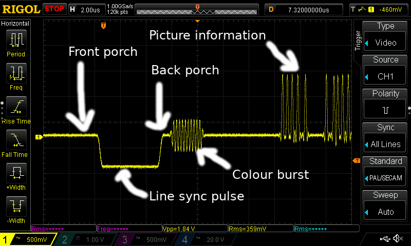
Immediately before and after the sync pulse itself are the short time periods referred to as the front porch and back porch respectively. These are the periods during which the picture information has stopped but the line sync pulse is not in progress, and they exist to demarcate the sync pulse from its surroundings and aid its detection.
Directly after the back porch is a short period of a pure sine wave (called the colour burst) that is at the frequency of the colour subcarrier. This so-called colour burst exists to allow the reference oscillator in the colour decoder circuit to be phase-locked to the one used to encode the colour information at the source. Each and every line that is not part of the frame blanking period will carry a colour burst, ensuring that the reference oscillator never has the time to drift out of phase.
After the colour burst there follows the luminance information for that line of the picture, with higher voltages denoting more brightness. Across the whole period from front porch to the start of the luminance information, that old CRT TV would have generated a line blanking pulse to turn off the electron gun while its target moves back across the screen to start the next line — the perfect time to transmit all of this important information.
Where Do All Those Figures Come From?
We’ve avoided specific figures because the point of this article is not to discuss individual standards. But it is worth taking a moment to ask why some of those figures come into being, and the answer to that question lies in a complex web of interconnected timing and frequency relationships born of a standard that had to retain backward compatibility as it evolved.
The frame rate is easy enough to spot, being derived from the AC mains frequency of the countries developing the standards. PAL and SECAM have a 50 Hz frame rate, while NTSC has a 60Hz one. The line frequencies though are less obvious, being chosen to fit the limitations of electronic frequency dividers in the mid 20th century. When there were no handy catalogues of 74 series logic, any frequency multiples between line and frame rates for the desired number of lines had to be chosen for simplicity in the divider chains required to link them in synchronisation from a single oscillator. As an example, the PAL system has 625 lines, with each 625 line image in the form of two interlacing frames of 312 and then 313 lines. The studio would have had a 31.250 kHz master oscillator, from which it would have derived the 15.625 kHz line frequency with a single divide-by-two circuit, and the 50Hz frame frequency with a chain of four divide-by-5 circuits.
Meanwhile the frequencies of the colour and sound subcarriers require a different view of the composite signal, in the frequency domain. The video spectrum is full of harmonics of the line frequency at regular intervals, and any extra carriers would have been required to have been chosen such that they did not interfere with any of these harmonics or with other carriers already present. Thus seemingly odd figures such as the PAL 4.43361875 MHz colour subcarrier frequency start to make sense when you view them as lying between line harmonics.
That a composite video signal can contain so much information while retaining the ability for it to be extracted by mid-century technology and furthermore to be able to be explained in a single page, is a testament to the inginuity of its many designers who added to its specification over the years. There was no one person who invented composite video, instead it is the culmination of the work of many different teams from [John Logie Baird] and [Philo T Farnsworth] onwards. It is unlikely that there will be further enhancements made to it, and it is probable that over the next decade or so it will march into history. For now though there is still a benefit to having a basic understanding of its components, because you never know when you might need to hack a display onto a microcontroller that happens to have a spare I2S interface.


Why bother with analog video when you can use HDMI od RS232
HDMI has too fast a clock rate and causes complexities when you want lower resolutions.
HDMI is best left to large CPLDs or FPGAs.
Next down from there is VGA – meaning QVGA, VGA, SVGA, XGA, WXGA etc
All of this article relates to VGA as well. Early VGA monitors were CRTs and needed accurate timings as they used relays to switch capacitors and instructors in and out of the timing circuits like the horizontal deflection circuit.
Modern LCD VGA monitors are far less picky at least with horizontal dot rate and sync timing though the like the total number of lines (including frame sync) to be one of the standards like as per 240, 320, 360, 400, 640, 800
When you press the “auto adjust” it will look for the first position a pixel appears on any line and the last position a pixel appears on any line and use that as the width specification.
The dot rate can be practically anything lower than the normal resolution but is best as an integer division. 1/2, 1/4, 1/8 etc
I saw one clever engineer on HAD.io that put a pixel at the start and end of the last offscreen line of the frame sync period so it wouldn’t show but at the same time is set the width without needing to press auto adjust.
A basic VGA generator can fit onto a very small CPLD. I have made one using a 72 macro CPLD with a fast serial flash chip as character ROM (the type normally used as a FPGA config chip). Modern and larger CPLDs are mor than enough.
As an example you can use 800×600 72Hz 50MHz standard and run the pixel clock at 25MHz instead of 50MHz to get 400 pixels or 80 characters that are 8 pixels wide. You can then repeat every second line to get 300 lines or 37.5 characters of 8 (16) lines height.
Things like this are even achievable with a mid range micro-controller. You only need some counters timers and perhaps a parallel to serial converter for higher resolutions.
More info on timings – http://martin.hinner.info/vga/timing.html
funny is that – as i observed – many flatscreen monitors do have a wild problem displaying 640×480@50Hz, a resolution we used in a former workplace often, obviously for display on CRT-TVs. 640×480@60Hz worked on most, yet the solution to that problem gave headaches “which monitor do you have? – and when will they fail?…..”
TL;DR 50Hz was never a VGA frame rate. It related to the era when MDA and EGA adapters had a composite output to drive a TV (via a RF modulator) 50Hz was supported for PAL and 60Hz was supported for NTSC.
Some early monitors supported 50Hz for compatibility but 50Hz was never a part of any VGA standard.
And IBM conformed to that standard … but no one else did.
MDA was propitiatory IBM. Then come the IBM clones from which EGA and CGA were created. CGA was the last standard that supported 50Hz by specification.
Some non IBM monitor manufacturers supported the 50Hz CGA frame rate for reverse compatibility reasons but 50Hz was never a part of industry accepted VGA standards even if it was some part of IBM VGA standards that I have never known of.
True fact: even on most of today’s HD camcorders, the LCD screen is an NTSC model. It just costs too much to do full HD at that size.
So where on my 45g micro quadcopter do I put the HDMI?
The color burst is important because it provides a PHASE reference (as well as frequency) at the start of every line.
There’s a crystal oscillator in the TV, so frequency is pretty stable, but phase is *very* important, because the phase of the color subcarrier is what determines the HUE (color). Amplitude determines the SATURATION.
And the frame rate for NTSC (Never Twice the Same Color) is related to the color burst frequency and the line frequency:
Line frequency:15.734 kHz = 3579545 / 227.5
Frame rate: 29.97 Hz * 2 = 59.94 Hz =
http://www.ni.com/white-paper/4750/en/
In case it’s not clear, the instantaneous color subcarrier phase is compared to the phase of the local color oscillator in the set, and the phase difference determines the color displayed.
You’ll see some color bars if the set is displaying a black/white vertical line pattern of just the right spacing to mimic the color subcarrier. An old b&w test pattern like this will show color bands where the (almost) vertical lines get closely spaced near the center of the image:
https://upload.wikimedia.org/wikipedia/commons/d/dc/RCA_Indian_Head_test_pattern.png
Wow, we really Have come a long way. I think that might be the first time I ever saw that pattern without blurring in the B/W days, or color artifacts from phase shifts, multipath, and convergence errors. Funny, on this LCD, it’s essentially perfect. Spoiled, we are, grasshopper.
What I never understood is why the tint control was needed in NTSC. I mean: you are receiving a sample of the color carrier, and it is supposed that any phase change between transmission and reception should affect both to the color burst and the color signal, so they should keep the relative phase… Why this wasn’t true?
I don’t know if this is the answer to your question, but the Tint control could compensate (a little bit) for an aging electron gun. So, if the picture is aqua colored instead of white, (weak red gun) you could shift it a bit toward the red.
Thanks, but that’s not the answer, I’m afraid. I’m pretty sure that it can also be used for that, but that wasn’t the original idea.
If you know that’s not the answer, then what is?
I know that, in origin, it was to manually adjust the tint, for example when changing from one channel to another. But what I don’t understand is why it was needed to manually adjust the tint in those cases if the signal already had a phase reference and the oscillator should be able to lock into it and make the control unnecessary.
Ancient history. NTSC was born the same year I was. A tint control can help compensate for non-linear phase errors in transmission. Research ‘differential phase’. Also, just about everything that handled video in a broadcast plant had an adjustment to establish correct phase relationship between chroma carrier and color burst. Every time you put a knob on something, you are asking for it to be mis-adjusted by a human in the loop. By the time video reaches the consumer’s receiver, hard telling how much damage has been done. You’d better give the viewer a way to compensate. ATSC fixed all that. It’s amazing that in 1953 we could deliver a real-time color image from point A to point B using simple analog concepts. It’s amazing that in 2018 my iPhone can do more than an entire semi-trailer filled with mobile studio equipment.
I found it! https://en.wikipedia.org/wiki/Differential_phase
Thank you very, very much!
Keep in mind that there were no digital phase-locked loops in the early color TVs. They could lock to the frequency of the color burst, but not really the phase. The lock was an analog feedback loop, meaning that it would always have a DC error proportional to the frequency difference between the crystal’s natural frequency and the colorburst it was locking to. This would show up as a phase error in the oscillator. And since every station used its own (imperfect) color carrier reference, the voltage it would take to lock the loop would be different for each channel, thus the phase error would be different. Detecting the phase of the color burst and comparing that with the phase of the set’s crystal oscillator, and then adjusting color accordingly, would have taken way too much electronics, and then THAT would have to be adjusted. Later TVs using digital color processing chips did a much better job, and some of them didn’t have the tint control. On ones that did, this was probably just a marketing thing, because people would have asked, “how can I adjust the tint? there’s no tint control”. People in general didn’t set up their tint and color controls for accurate color; they adjusted them for what they THOUGHT the picture should look like. Which more often than not meant bright red faces. Don’t ask me why.
Acutally, in older TVs, the color burst is NOT part of a PLL system. It’s not PHASE locked, instead it is INJECTION locked. The crystal frequency is precise enough to be a good reference for at least one entire scan line (63.5us). To establish proper phase during the color burst reference interval, a gate briefly overdrives the local crystal oscillator (injection), and it will be accurate enough as it free runs for the rest of the scan line.
Regarding TINT. Consider that 360-degrees has to encompass the entire spectrum of colors, even a small phase difference might be a noticeable shift in color. So the TINT adjustment makes up for parts tolerances in the receiver as the user does the final fine adjust. The PAL system somewhat avoids this as the Phase Alternating Line means that the error will alternate from line to line and from any reasonable viewing distance the error will average. For example a yellow region might appear slightly red on some scan lines, but slightly green on alternate one. Net effect: it’s proper yellow.
PAL however has it’s own set of problems. But the development of the 1-H horizontal ultrasonic delay line for the PAL system, found an alternate using in NTSC as part of a color separation filter that improved NTSC.
Color shift is a particular problem for fleshtones and food. Nature designed us that way. We avoid jaundiced people (diseased) or off-color food (spoiled). That’s why color calibration is so important in advertising involving people and food, but less so for cars, or landscapes (is that sky *really* that color of blue?).
That’s most of the story but it only mentions phase distortion caused by the non-linearity of electronic components (at the transmission end).
The other half of the story is that the band chosen (VHF) had some interesting characteristics. Lower frequencies than VHF could achieve “over the horizon” transmission paths by bouncing off the ionosphere which meant the transmission path was more or less two straight vectors.
Higher frequencies like UHF were more or less “line of sight” which made them also more like a single vector and UHF was very poor for over the horizon transmission,
VHF transmission could curve somewhat and achieve over the horizon that way but ground reflection or reflection from other objects like tin roofs on buildings would cause phase distortion. This was non-linear as the amplitude of the color burst is fixed while the amplitude of the color information varied. Also environmental conditions such as damp ground from rain or different signal paths from transmitter to receiver caused variations.
So for NTSC the tint control was used to manually correct for phase (color) distortions.
This wasn’t necessary for PAL (Phase Alternate Lines) because the phase distortion of one line was canceled out by the next line.
When TV manufacturers started to manufacture TV’s for different standards we even saw a “tint” or “colour” control on PAL sets because it was easier to use the same cabinet design that had the extra control. However on PAL sets this control had a completely different purpose. It balanced the relative amplification of color as compared to luminescence and only need be set once to the users preferred setting.
IIRC the reason Sony TVs in Europe had a tint control was because they did not want to pay the PAL system licence fee and had the control knob instead of following the standard (I.e. automatic colour correction)
In addition diff phase, let’s not forget what phase offset errors could occur within the local PLL. All things considered, the tint control compensated for a constellation of issues. The relatively newer PAL system, by cunning design (and at increased receiver cost), dropped the tint control and traded tint errors for the less apparent changes in color saturation.
Of course PAL is superior, not only having 100 extra lines of vertical resolution (625 instead of 525), but alternating the phase of the colour subcarrier on alternate lines so as to cancel out phase errors. No tint control provided or needed!
Lets not forget NTSC-M (US market) equipment lacking component/RGB/and often even SVideo IO. Because why bother when you broadcast/record NTSC diarrhea anyway.
Meanwhile Euro/Japan came with RGB signalling standard from the 80s onward(SCART/JP21), great for early computers, consoles and high quality recorded media.
Yes and nothing beats that 50Hz euro-flicker and those delightful Hannover bars! lol
Later PAL TVs (at least high end ones) used an internal frame buffer and displayed at 100 HZ, to solve the flicker problem.
This is seen as the major advantage of PAL over NTSC, but it’s not that simple. Yes, any color error gets averaged out over two fields, but this results in reduced color saturation. If a certain area is supposed to be pure red, for example, if there is a big phase error, it will be orange on one field and magenta on the other, and the average won’t be pure red, it will be a muddy red.
There is a very simple explanation for most of the differences in standards – they were invented at different times. Each system was the best that could be produced at a sellable price at the time it was invented. The rest (Secam for example) is just ‘not invented here’.
or to be exact, it’s 30,000 / 1001.
er. that was in response to the 29.97 Hz thing way up above.
The burst also supplies a standard amplitude, used for saturation.
reminds me of the good old real mode x86 days where there wasn’t enough memory to do double buffering and we had to wait for the vertical retrace to quickly do the updates in the frame buffer. There was also no VBLANK interrupt, so we had to poll an IO port (3DAh, bit 3), wasting lots of CPU cycles.
Thomas “Tran” Pytel was Clever and abused the PC’s 8254 to make a phase-locked loop synchronized to the vsync pulses, reducing the amount of time he had to poll.
You can see this if you play with his crazy 21bpp flickervision demos (Luminati / Ambience) in dosbox’s debugger
ha, that is absolutely genius, there was so much talent in the demo scene back in the day. Everybody had so much fun in mode 13h (INT 10h). I spent quite some time trying to get more performance in the higher resolutions, minimizing bank switching etc, before later finally moving to protected mode. good memories!
Good start. Lots of other things to cover tho…black level/pedistal, color subcarrier extraction, etc.
I’ll take a stab at pedestal. This was an American cheat that made TVs cheaper. By setting black at 7.5 IRE units above the zero level, known as pedestal, this put the actual zero level at “blacker than black”. This made it possible for some manufacturers to not blank the CRT guns during retrace. Note that in IRE units, the luminance signal ranges from 0 (blacker than black) to 100 (pure white).
The Japanese were much more proper; they would never dream of this kind of hack, so they set their black level at 0, and properly gated the CRT guns off. This is the only difference between NTSC-J and NTSC-M (the American system).
Wait a minute. I wonder if this is one of the historical reasons behind stupid HDMI 16-235 Video level resulting in crappy picture when not paired correctly with PC monitor (which expects normal 0-255)
Yes, it is. It’s also the source of MANY errors in NTSC capture devices. Some expand the luminance to 0..255, and others don’t, and the same ambiguity exists in converting back to NTSC. So if you’re editing NTSC content in a non-linear editor and recording back to NTSC tape, if the codecs don’t match you either get gray blacks or clipped blacks.
I’ve even run into this when using the JPEG codec in Final Cut Pro 7: I needed to do some retouching of scenes in a feature film, and my tools were bitmap based. So I asked the director to send me a .mov file using the JPEG codec so I wouldn’t be going through multiple codecs. The frames looked fine when I edited them, but when I sent them back to him, FCP 7 mis-read the frames and clipped all of the blacks! This was like four years ago, not exactly ancient history.
Brings back memories. Technically, the entire ‘shelf’ following the H sync pulse is the back porch. When color burst was added it was placed in that area, and the small portion labeled ‘back porch’ in the graphic became known as ‘breezeway’.
Ah, you live and learn. Am relying on years of fixing old TVs not standards gurudom.
“When you acquired your first oscilloscope, what were the first waveforms you had a look at with it? The calibration output, and maybe your signal generator. Then if you are like me, you probably went hunting round your bench to find a more interesting waveform or two. In my case that led me to a TV tuner and IF strip, and my first glimpse of a video signal.”
I still miss my TV handbook. You could club someone senseless with it.
https://www.amazon.com/Television-Engineering-Handbook-TELEVISION-ENGINEERING/dp/007004788X/ref=sr_1_1?s=books&ie=UTF8&qid=1516302456&sr=1-1
Found it.
It also should be pointed out that the ‘inverted’ pulses in the V interval serve another purpose. They allow continuity of H timing in a system that has an odd number of lines per frame (525, 625). The V interval is offset by 1/2 line time in ‘odd’ vs ‘even’ fields.
For anyone wanting to do more research, the term of art for the faster sync pulses is “serration sync”.
That may be one term, but the official one was “equalization pulses”.
I think you’re both correct. The qualization pulese are those that occur during the 1/2-H locations and these assure proper interlace. The region where the H-sync has lines of added equalion pulsed before, during, and after the v-sync perion, is the serrated sync region.
Teletext and CC are not in the frame blanking period, they’re on line 23 and 21 respectively (iirc). Technically part of the video, but off the top of an analogue CRT due to the overscan
Thanks for this. Looks like all we old farts who were there and know a thing or few just self-identified. Good to know there are still a few of us around….
National had a good tutorial on all this in one of the late 70’s linear apps books. They were trying to sell chips into the market when there still was one in the US.
I was in a funny place when I first played with scopes and this class of signals. Born in ’53 to a an EE working at NRL who had a pretty nifty home lab he let me play in with him. We didn’t actually get a real TV till much later on – my parents were already suspicious of “programming” (now known as spin or even fake news). And…they were right I suppose. We got a PDP-8 instead. I was a lucky kid – my mom, and experimental psychologist, taught me FORTRAN. Some would say unlucky as most of this came at the expense of the social graces – I was a pure nerd from the git-go but socially retarded for life.
Why tell all this. Maybe to set up the classic line – when as a teen I fixed this kinda thing for a “get out of the parent’s house and buy a car job” – here’s why there’s a tint control – NTSC stands for “Never Twice the Same Color”.
This is an excellent trip down memory lane for sure for this broadcast television engineer from many moons ago. Now what I’d love to see is a write-up of the color phase differential, complete with waveforms from a *vectorscope*. That was the key piece of gear that allowed us to ensure that all cameras had the exact same color reproduction (quite the chore on a shoot with 20 cameras and changing lighting conditions, like a baseball game going from day to night).
And then how about discussing Time Base Correctors (TBCs). They allowed you to adjust the phase of cameras so that they were in synch; different lengths of camera cable (Tri-Ax) meant the signals got to the switcher at different times (speed of light and all that), so the signals had to be adjusted to be perfectly in time with each other.
Let’s get truly nerdy here!
Geez. I had about three paragraphs on this, and then it disappeared. Isn’t digital wonderful?
Anyway, as you say, vectorscopes were used to match color between multiple cameras and other video sources. This is the graticle for a vectorscope, with the bold geometric figure being how standard SMPTE bars were displayed. http://www.cameratim.com/electronics/panasonic-wv-f15-camera/images/vectorscope-colour-bars.png.
The vectorscope was just an oscilloscope with the demodulated color carrier’s components displayed on its X and Y axes. The color burst showed up at the 9 o’clock position on the screen, in the center of the cross-hatched area. The “I” phase of the carrier was adjusted to line up near the 11:00 position, and “Q” phase at about 2:00. Distance from the center of the screen indicated color magnitude, which was very useful for setting up cameras: to compensate for the colors of different light sources, you could hold a white piece of paper in front of each camera, and adjust that camera’s red and blue gain to center the dot on the screen. Red gain moved it vertically, blue horizontally. Eventually this manual procedure got automated, by adding a “white balance” button to camera control units. If you were better than me at this, you could identify something you knew the color of, and adjust that to the proper place on the screen in a pinch, like if you had nothing white to point at, or couldn’t take the cameras off line.
Some modern, digitally based live switching systems and video editors still have vectorscope displays available, but these are simulations, since there isn’t any actual color carrier to decode. But these are still useful for adjusting whie balance on the fly when necessary.
I couldn’t find a picture of an actual CRT vectorscope display, but this is a picture of a fair simulation, with the picture that this is a vector display of, up in the corner. http://www.drastic.tv/images/software/4kscope/screenshots/4kscope_vectorscope_1080.png. The big green finger pointing almost straight up is the red from the red/magenta umbrella, the big blob in the midle of the screen is the gray of the sidewalk, street, cars, and other neutral stuff. But the most important thing on the display is the smaller finger pointed toward the upper-left. That’s the characteristic skintone color, which is showing up because of the four legs and one arm in the picture. Since this is a simulated display, the developers thought it was useful to show a line where skintones ought to be. You’d never see this on a real CRT vectorscope.
I had the luck to be working on TV test generators and scopes at Tektronix when they introduced their first timebase corrector, the 110-S. They introduced these just in time for the 1984 Olympics in Los Angeles, and just in time they were – the games were spread out all over the county, making it practically impossible to send black burst (genlock) to all of the shooting locations. So instead, they ordered HUNDREDS of these TBCs to synchronize the cameras at the central broadcast center. TBCs worked by decoding the analog composite signal into Y (luminance), R-Y, and B-Y signals, digitizing each of these, and storing them in dynamic RAM. These could then be read out in synchronization with the master black burst for the center, converted back into analog, and sent through conventional analog switches. The incoming side still had to be calibrated using color bars, but what came out was synchronized in both position on the screen and color phase. I was being considered for being sent down to supervise the operation of these, but I was in Santa Clara, California, and they had a qualified tech in Irvine who got the gig instead.
I’ve done camera matching using vectorscopes as recently as about two years ago – I made the mistake of helping somebody to set up a portable production system made up of an Echolab DV5 “digital” (but all analog inputs) broadcast switcher and a pair of 2-channel Digital Processing Systems TBCs that he picked up at an auction, and now I’m his go-to guy whenever it has problems. Fingers crossed – maybe he’s upgraded to by now.
Does this work?
Just had to try. Old dog.. tricks.
I use Chrome and the “Clipboard History” extension to save what I write and post just in case for later reference.
This is the best Vectorscope Waveform Monitor presentation I’ve ever watched: https://www.youtube.com/watch?v=z-UBLJdd2g0
Really detailed and clearly explained. Granted is from a different era… though I picked up a $8 Tektronix 1740 from the GVSU Surplus Store for the rackmount case and components. Interesting reading into and studying more though and the new systems like the Leader combined systems are impressive. Neat learning regarding tapping into the A11 board to make a VGA output, and I think I am going to make an RCA output also while at it, for the TDS-520.
Yeah but what about the sexily named infinite window TBCs?
Nurdy enough?
Dis the quality of NTSC all you want. But when you read in detail how the various components of the NTSC signal were devised, and how they got shoehorned into the limited bandwidth while not breaking existing monochrome systems, you can’t help but admire the engineering prowess of the originators. Every time I look back at it I’m reminded of their genius.
One example is the interleaved harmonics already mentioned. Another simple one is the recognition that the sidebands are redundant and a waste of bandwidth and transmitter power, so the signal is transmitted with most of the lower sideband suppressed — not quite single sideband. So-called vestigial sideband (VSB).
But my favorite is the actual colour encoding. The colour subcarrier (at the colourburst frequency) uses both sidebands, but encoded with Inphase and Quadrature components. As described above, the phase of that I & Q signal specifies the colour at that instant in the scanline. The I & Q represent the RGB component of the signal, but rotated in the 2D space. The Inphase represents the colour on an axis something like orange-cyan, and the Quadrature represents green-purple. What I think is really neat is that the bandwidth of each component (I and Q) is *different*.
Like the vestigial sideband of the luminance signal, the spectrum is not centered on the carrier. However, in this case of the colour signal, the (sub)carrier is being modulated by a *complex* (I & Q) number, so both sidebands are required. The genius of the NTSC engineers is in recognizing that the human eye is better at discerning differences along that orange-cyan axis than the purple-green axis, so more bandwidth is allocated to the sideband representing the I signal. Genius, and damned good engineering.
I agree Paul,
Even the recognition that more time is spent transmitting white than black, so max video signal level (white) corresponds to minimum carrier amplitude (inverted), so less power needed over a period of time. Simple but clever.
Ah, yes, I forgot that one. Another really neat part of making “white” be low amplitude and black be high, is that the noise floor happens in the *white* part of the image, where the noise is not very visible. Black is a high amplitude, low-noise signal, so looks better.
Remember, this was in the days of slide rules and pencil and paper. No fancy simulators, no matlab filter designer tools, no DSP toolkits. Engineering then required skullsweat and deep understanding of the math and physics involved, and a good appreciation of the limitations of electronics. Even the test equipment required real thinking to operate.
I inherited a set of wonderful book compilations of papers from that era: “The Lenkurt Demodulator”. It’s fascinating reading, for a radio electronics geek. Can be found at quality libraries and probably yard sales near you.
Engineering still does even if the problem domain has changed. But it’s good to appreciate the past even if some thinks it means primitive.
The main reason for inverting the video for transmission was so the sync pulses would be at max power, hopefully allowing even a weak snowy image to lock.
Viewing of UK 405-line TV that had positive-going video (white = max carrier amplitude) was for years plagued by interference from nearby vehicles’ spark ignition that appeared as superimposed white spots; some 405-line TV receivers were equipped with an adjustable white limiter (spot clipper) to alleviate the problem. The immediate advantage of the change to negative-going video for viewers was removal of these white spots; they became relatively innocuous black spots that do not spread. This improvement was achieved before the introduction of compatible colo(u)r TV, and I don’t see long-term saving in transmitter power as a significant motive for the change; obviously any TV transmitter must be designed to be capable of sending an all-white picture indefinitely.
This is an excellent trip down memory lane for sure for this broadcast television engineer from many moons ago. Now what I’d love to see is a write-up of the color phase differential, complete with waveforms from a *vectorscope*. That was the key piece of gear that allowed us to ensure that all cameras had the exact same color reproduction (quite the chore on a shoot with 20 cameras and changing lighting conditions, like a baseball game going from day to night).
And then how about discussing Time Base Correctors (TBCs). They allowed you to adjust the phase of cameras so that they were in synch; different lengths of camera cable (Tri-Ax) meant the signals got to the switcher at different times (speed of light and all that), so the signals had to be adjusted to be perfectly in time with each other.
Let’s get truly nerdy here!
https://youtu.be/3JFt6t6ijLs
Sorry, I’ve watched this guy’s channel before, not interesting. Its basically just watching him read a Wikipedia article. What’s the point of having a video just to watch lips move.
Can anybody illustrate me on how hard would it be to “parse” PAL/NTSC with an esp8266 (via ADC input?). I mean the opposite of emitter projects like this one: https://github.com/hrvach/espple?
Pretty much impossible without a lot of extra hardware. Kind of like bringing a wet noodle to a gun fight.
“by the book” you’ll need to digitize the full bandwidth of the signal with reasonable dynamic range. A reasonable choice would be 4x the colourburst frequency, at 8 bits.
One trick some older frame digitizers used was to use a sample & hold once per line (i.e., at 15.7 kHz), and digitize at that rate, delaying the phase on each frame to eventually (over many seconds) collect the whole image. I don’t think you can reasonably expect accurate colour using this method.
Can you persuade a esp8266 to digitize at 16 kHz and store several seconds of data at that rate?
16kHz sampling rate? That gives you a single pixel per horizontal row. To have even a really low horizontal res (like 256) you’ll need something closer to 5MHz.
Yes… a single pixel per line (“row”).
The window width of the sample & hold makes that single pixel arbitrarily small though (that’s what the sample & hold is *for*), and by shifting the phase on subsequent frames, you build up an arbitrary number of pixels per line.
My apologies if it wasn’t perfectly comprehensible first time ’round.
In practice, in NTSC, these digitizers at the time captured typically 240 lines x 320 pixels over a few seconds (320 fields = 5. 3 seconds).
I got it working in the early-90’s on a PC with just a free-running ADC at 20 kHz or so: a very simple matter of rebinning the resulting byte stream into a rectangular array. Not terribly useful, especially since I had a Matrox card handy, but a fun hack.
Subsampling can work great, even for modulated input… if your signal is filtered strongly enough that there won’t be any aliases from unwanted signals.
I don’t know if you can get a good enough bandpass to use subsampling to decode TV, or if you’ll basically end up recapitulating the entire demodulation stage to do so. Subsampling is still an option for just baseband CVBS, if the picture doesn’t change with time.
i2s is bi directional on ESP, you can pump data in one bit at a time at 80MHz = 8MHz 8 bit, enough for good quality PAL. Ram and processing power might be a problem tho ;)
https://github.com/cnlohr/esp8266duplexi2s/
8MHz is just a little too slow for the nyquist rate for decoding the color signal out of PAL. You might be able to get away with intentionally aliasing and demodulating the alias from 3.566MHz instead
Awesome replies! My initial question was about **acquiring** that data. So if RAM and processing power are a problem on-chip, how feasible would it be to send whatever is gathered as soon as possible via the ESP’s WIFI somewhere else for more heavy duty post-processing?
no, whole esp8266 maxes out at around 10 MBit/s. Radio part of the chip at 28 Mbit/s, after you skip internal 802.11 and TCP/IP stacks – for example connecting it to Pee over SDIO.
You could maybe reach ~5-10 fps at B/W QQVGA (160×120) resolution.
mind you, you will need external ADC and some kind of serializing chip(shift register).
Not very cost effective, seeing as the cheapest CCTV camera modules are ~$5. $10 Pee Pi Zero availability W + $5 Pee camera module will be ~same price overall while streaming 25Hz 1080p with no problem.
Awesome!
This (article and comments) is exactly the type of information one would need to understand this chip
http://www.vlsi.fi/en/products/vs23s010.html
and this project (shameless self plug)
https://hackaday.io/project/21097-arduino-video-display-shield
.
The VLSI VS32s10 is an awesome chip. I have some here and can’t wait to play with it.
Funny. My first scope job, which was a tube based beauty which my father built for B&H/.Devry Schools, was in figuring how linear circuits could do what they did. And that did include the odd square wave and triangle. Used to marvel at how close to a perfect sine wave the AC delivered by Con Ed was showing. It came with a 97.99% rating according to the scope graticule.
At least you mentioned good old Philo T. Farnsworth, jenny. Most people have no idea who he was, and think that guy at NBC invented B&W TV for RCA to make more money. PTF proved that he invented the ideas behind raster scan, and even found his teacher to back up his prior art claim.
“When you acquired your first oscilloscope, what were the first waveforms you had a look at with it?”
I still am not sure exactly though they were noisy (I am confident RF difference signals heterodyne’d to make sound signals audio though blended into the carrier to look like noise) Tetra looking lower case “m” signals frequency hopping around ~820MHz that correlated with the sounds I was hearing in my perimeter talking to me that I was watching very clearly using Spectrum Lab on the laptop. Lately, I find ultrasonic signals and haven’t been investigating if they’re coming in using microwave carriers as I’m trying to learn more detailed electronics repair, prototyping and systems to eventually get a 24-7-365 broad range scanning system operational.
Prior to that was in the Instrumental Analysis Lab course at Tech studying analog and digital signals. We even had to learn how to use a plotter and my first gas chromotagraph was displayed on a plotter. That was in 1999/2000 even… though most of my best courses required us to learn the history of what we were studying so we “know” versus “do” so to be be subject matter experts for the engineers.
I vote fiber optic more, wireless in healthy optical maybe signals or other healthy frequencies and not so much sickening and maddening wireless… this is getting ridiculous at least with what is always beamed, heterodyned, pulsed and targeting me and my vicinity. Awesome article and Philo T. Farnsworth deserves a write up some day.
Philo T Farnsworth does require a writeup. Most Brits will have been told that John Logie Baird invented TV, but he only made a form of mechanical TV work, the systems eventually employed owe far more to the work of Farnsworth.
As ever with these inventions no one person does it all from start to finish and so much is drawn on other people’s work.
Alan Blumlein is the guy i’d like to see a write-up on. Stereo sound, long-tailed pairs, electronic TV, RADAR… anyone?
Television signals are really a very impressive technical achievement, especially considering how early they were actually in use. A few blocks from where I grew up there’s a plaque marking the site of Philo Farnsworth’s early television experiments in the ’30s. An article on him would be very neat, I’m sure.
I know this is an older post now, but all this talk of scopes and vectorscopes reminded me of a (Windows) program I wrote about 10 years ago. Anyone who wants to play with a simulation of these that analyzes still images in roughly the same fashion can download the (now free) Photo Scope software at http://www.mdxi.com/demos/PicScope.zip.
Always happy to get comments and critiques.
For anyone who gets this fare and wants to know more about the numbers, I wrote this in 1979/80, and updated it in 2005 (even though it says 2015!). The final summary is now out of date. Maybe I will get round to updating it properly one of these days! And just for the record, I started my career in 1969 at the BBC as a Vision Engineer (Video) at their West London Studios (TV Centre & Lime Grove).
http://www.editorsbench.co.uk/documents/CF2015.pdf
That should be “.. gets this far ..”.
Nice write-up Jenny.
Ah maybe I was a bit younger than most when I got my hands of a scope. But at 11 or 12 yrs old the first thing I hooked up to my Dad’s scope he got from DeVry was a crystal microphone.
A couple years later a neighbor from around the block lived across the street from an open field, next to the original Vallco shopping center. ( think hp site & now Apple) anyway we would notice an echo of the mall buildings from firecrackers we would light off in the field. My buddy’s dad had a Tek scope, rolled that out of the garage set up with an extension cord, a crystal mic and popped a few firecrackers and what’s return echoes….cool.
The writer Jenny List should spell INGENUITY properly.