They lie at the heart of every fidget spinner and in every motor that runs our lives, from the steppers in a 3D printer to the hundreds in every car engine. They can be as simple as a lubricated bushing or as complicated as the roller bearing in a car axle. Bearings are at work every day for us, directing forces and reducing friction, and understanding them is important to getting stuff done with rotating mechanisms.
Rolling-Element Bearings
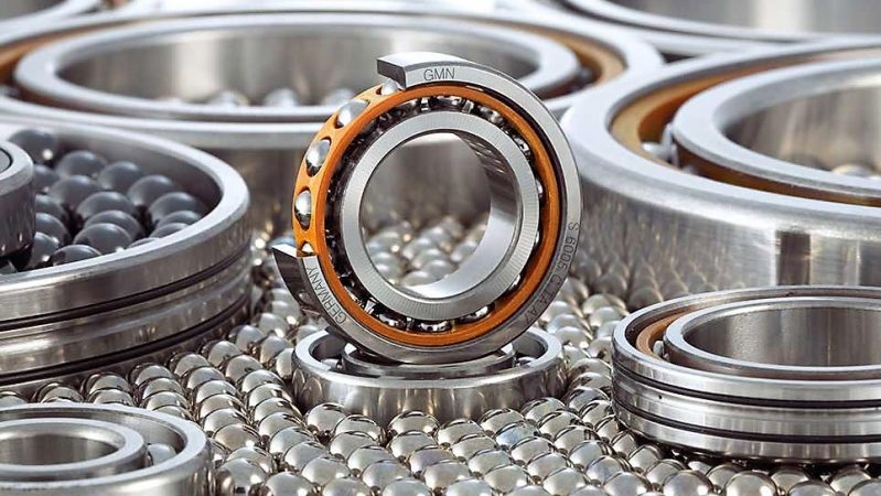
What first pops to mind when using the term “bearing” is probably something from the broad category of rolling-element bearings, like roller bearings or ball bearings. We’ve all seen them before — tough steel balls or cylinders trapped between two grooved tracks. Legend has it that Leonardo da Vinci invented ball bearings in the 1500s, but like many of his drawings, no practical implementation would be attempted for hundreds of years until advancements in material science and engineering caught up with his original vision.
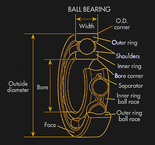
Rolling-element bearings rely on rolling elements constrained between inner and outer races to reduce friction and manage loads. There are two main loads for bearings: radial and axial. Radial loads on bearings are perpendicular to the long axis of the shaft. The force exerted by the shaft of a giant electric motor’s rotor on the case is an example of a radial load. Ball bearings are great at handling radial loads, but roller bearings, with more surface area along the roller than the point contact of a ball, are even better.
Neither is particularly good at handling axial loads, or loads parallel to the long axis of the shaft, though. An axial load might be a CNC router’s spindle being pressed up into the motor during an overly ambitious plunge cut with an end mill. Because the grooves in the inner and outer races of these bearings can’t be very deep, there’s not much for the rolling element to press against in the axial direction, resulting in poor performance in that dimension.
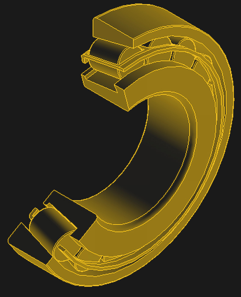
Tapered roller bearings are better at handling axial loads, somewhat at the cost of some radial load handling. Tapered roller bearings are exactly what they sound like — roller bearings where the inner race is shaped like a shallow cone, with a matching taper to the outer race. Tapered roller bearings handle high axial loads, but only in the direction that tends to jam the inner race into the taper of the outer race. If axial loads in both directions need to be handled, tapered bearings are usually used in opposing pairs.
There are, of course, lots of variations on the theme of rolling-element bearings. Sometimes there are two parallel races inside a single bearing for better load handling, or even opposed tapered elements so a single bearing can handle axial loads better. Extra parts like shields and seals can keep grit out or lubricants in. And while most roller and ball bearings are made from steel, other materials ranging from wood to plastic and even ceramics have been used. Ceramic ball bearings have some interesting properties:
Hydrodynamic Bearings
A much simpler type of bearing is the hydrodynamic bearing, or plain bearing. A shaft rotating in a hole is the simplest example, although with direct metal-on-metal contact, such bearings are not long for the world in most practical cases. Most hydrodynamic bearings rely on the properties of fluids to achieve the goals of reducing friction and managing loads. Grease or oil are the most common fluids used as in hydrodynamic bearings; the lubricant forms a film between a shaft and the bearing surface that prevents metal-on-metal contact and is capable of transmitting a huge amount of radial load because of the incompressibility of fluids.
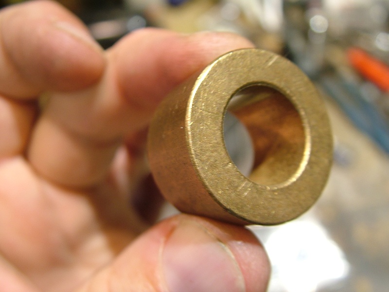
One common hydrodynamic bearing is the sintered bronze bearings found in many hobby motors and servos. Bronze particles are pressed and heated into a porous cylindrical shape with a bored out center. The motor’s shaft passes through the bore, and oil that has soaked into the bore provides the fluid film needed to reduce friction. Plain bearings are also found in internal combustion engine crankshafts, both at the ends of the connecting rods and between the crankshaft and crankcase, and are usually lubricated indirectly through splashing or by oil pumped under pressure through small galleries. In general, plain bearings like these have a layer of softer metal between the rotating parts to prevent damage if the engine is starved for oil, and to facilitate replacement during an overhaul.
Of course, this barely scratches the surface of the field and completely misses fascinating bearings like magnetic bearings where the metal-on-metal contact is prevented by magnetic repulsion, or fluid bearings that use a pressurized gas or a liquid to hold a shaft apart from a journal. But these are at least a few of the most common bearings, and a little of the engineering behind the mechanisms.
Featured image source: GMN Paul Müller Industrie GmbH & Co. KG


The largest bearing anywhere, is a railroad track. Early track failures led to extensive research on metal fatigue, and was compared to a bearing spinning. (Load, unload, repeat)
Also they discovered by about 1840 that using granite ties (or “sleepers”) under the rails didn’t work as well as wooden ones. We can now understand that the stone would reflect high-frequency energy that the wood would absorb.
I was wondering about why they didn’t use those!
Thanks!
And this is why modern concrete ties generally have a damper built into the system, often an elastomer pad between the clip plate and the beam. Without damping, the concrete crumbles. There also needs to be some compliance, both in the beam (wood, reinforced concrete, but not particularly granite) and the substructure (packed gravel ballast).
https://www.youtube.com/watch?v=5uxsFglz2ig
lmao not even close
http://i.imgur.com/qUjFEaN.jpg
@hap
Dream on, the “Race” of a railroad track can be thousands on miles long.
That little piece of junk in your picture is just a few feet across.
Wasn’t the rolling element bearing invented by the Egyptians when they used logs to move stone slabs during the construction of the pyramids?
And most likely the builders of stonehenge and others before them. I think they are mostly covering radial bearings.
Who the duck builds a stonehenge?
https://www.youtube.com/watch?v=Lf119qOXQaA
No wheels exist in nature.
Throughout history, most inventions were inspired by the natural world. The idea for the pitchfork and table fork came from forked sticks; the airplane from gliding birds. But the wheel is one hundred percent homo sapien innovation. As Michael LaBarbera—a professor of biology and anatomy at the University of Chicago—wrote in a 1983 issue of The American Naturalist, only bacterial flagella, dung beetles and tumbleweeds come close. And even they are “wheeled organisms” in the loosest use of the term, since they use rolling as a form of locomotion.
The wheel was a relative latecomer.
We tend to think that inventing the wheel was item number two on our to-do list after learning to walk upright. But several significant inventions predated the wheel by thousands of years: sewing needles, woven cloth, rope, basket weaving, boats and even the flute.
The first wheels were not used for transportation.
Evidence indicates they were created to serve as potter’s wheels around 3500 B.C. in Mesopotamia—300 years before someone figured out to use them for chariots.
The ancient Greeks invented Western philosophy…and the wheelbarrow.
Researchers believe that the wheelbarrow first appeared in classical Greece, sometime between the sixth and fourth centuries B.C., then sprung up in China four centuries later and ended up in medieval Europe, perhaps by way of Byzantium or the Islamic world. Although wheelbarrows were expensive to purchase, they could pay for themselves in just 3 or 4 days in terms of labor savings.
Art historian Andrea Matthies has found comical illustrations, one from the 15th century, showing members of the upper classes being pushed to hell in a wheelbarrow—quite possibly the origin for the expression “to hell in a handbasket.”
Wheel of Fortune: More than just a game show.
The Wheel of Fortune, or Rota Fortunae, is much older than Pat Sajak. In fact, the wheel, which the goddess Fortuna spins to determine the fate of those she looks upon, is an ancient concept of either Greek or Roman origin, depending on which academic you talk to. Roman scholar Cicero and the Greek poet Pindar both reference the Wheel of Fortune. In The Canterbury Tales, Geoffrey Chaucer uses the Wheel of Fortune to describe the tragic fall of several historical figures in his Monk’s Tale. And William Shakespeare alludes to it in a few of his plays. “Fortune, good night, smile once more; turn thy wheel!” says a disguised Earl of Kent in King Lear.
Camels 1; Wheel 0
Camels supplanted the wheel as the standard mode of transportation in the Middle East and northern Africa between the second and the sixth centuries A.D. Richard Bulliet cites several possible reasons in his 1975 book, The Camel and the Wheel, including the decline of roads after the fall of the Roman Empire and the invention of the camel saddle between 500 and 100 B.C. Despite abandoning the wheel for hauling purposes, Middle Eastern societies continued to use wheels for tasks such as irrigation, milling and pottery.
“Breaking on the wheel” was a form of capital punishment in the Middle Ages.
This type of execution was medieval even by medieval standards. A person could be stretched across the face of a wheel and bludgeoned to death or have an iron-rimmed wheel pounded across the person’s bones with a hammer. In another variation, Saint Catherine of Alexandria was wrapped around the rim of a spiked wheel and rolled across the ground in the early fourth century. Legend has it that the wheel “divinely” broke—sparing St. Catherine’s life, until the Romans beheaded her. Since then, the breaking wheel has also been called the “Catherine Wheel.” St. Catherine was named the patron saint of wheelwrights.
The oldest, most common design for a perpetual motion device is the overbalanced wheel.
For centuries, tinkerers, philosophers, mathematicians and crackpots have tried to design perpetual motion devices that, once set in motion, would continue forever, producing more energy than they consume. One common take on this machine is a wheel or water mill that uses changes in weight to continually rotate. The overbalanced wheel, for example, has weighted arms attached to the rim of the wheel that fold down or extend out. But no matter what the design, they all violate the first and second laws of thermodynamics, which state, respectively, that energy cannot be created or destroyed and that some energy is always lost in converting heat to work. The U.S. patent office refuses to assess claims for perpetual motion devices unless the inventors can produce working models.
Life, liberty and the pursuit of patents.
According to the U.S. Patent and Trademark Office, the first patent involving a wheel was issued to James Macomb of Princeton, New Jersey, on August 26, 1791—just one year after the U.S. Patent Law was passed. Macomb’s invention was a design for a horizontal, hollow water wheel to create hydropower for mills. Although the patent office is aware of this patent being issued, the original record was destroyed along with other patents from the 18th century in an 1836 fire.
The earliest wheels in North America were used for toys.
In the 1940s, archaeologists unearthed wheeled toys—ceramic dogs and other animals with wheels as legs—in pre-Colombian layers of sediment in Vera Cruz, Mexico. The indigenous peoples of North America, however, would not use wheels for transportation until the arrival of European settlers.
Roulette means “small wheel” in French.
The origin of the gambling game roulette is a bit hazy. Some sources say Blaise Pascal, a 17th-century French mathematician, invented it in his attempts to create a perpetual motion device. But what’s more commonly accepted is that roulette is an 18th century French creation that combined several existing games.
The term “fifth wheel” comes from a part that was often used in carriages.
By definition, a fifth wheel is a wheel or a portion of a wheel with two parts rotating on each other that sits on the front axle of a carriage and adds extra support so it doesn’t tip. But it’s superfluous, really—which is why calling someone a “fifth wheel” is a way of calling them unnecessary, basically a tagalong.
How the bicycle ruined enlightened conversation.
As reported in the New York Times, an 1896 column in the London Spectator mourned the impact of the bicycle on British society: “The phase of the wheel’s influence that strike …most forcibly is, to put it briefly, the abolition of dinner and the advent of lunch….If people can pedal away ten miles or so in the middle of the day to a lunch for which they need no dress, where the talk is haphazard, varied, light, and only too easy; and then glide back in the cool of the afternoon to dine quietly and get early to bed…conversation of the more serious type will tend to go out.”
The first Ferris Wheel was built to rival the Eiffel Tower.
Norman Anderson, author of Ferris Wheels: An Illustrated History, surmises that the first pleasure wheels, or early Ferris Wheels, were probably just wheels with buckets, used to raise water from a stream, that children would playfully grab hold of for a ride. But it was the “revolving wheel, 250 feet in diameter and capable of carrying 2,160 persons per trip,” invented by George Washington Gale Ferris, Jr. and unveiled at Chicago’s World Columbian Fair in 1893, that really brought the Ferris Wheel to the carnival scene. The fair celebrated the 400th anniversary of Columbus’s discovery of the New World, and organizers wanted a centerpiece like the 984-foot Eiffel Tower that was created for the Paris Exposition of 1889. Ferris answered that call. He apparently told the press that he sketched every detail of his Ferris wheel over a dinner at a Chicago chophouse, and no detail needed changing in its execution.
In movies and on TV, wheels appear to rotate in reverse.
Movie cameras typically operate at a speed of about 24 frames per second. So basically, if a spoke of a wheel is in a 12 o’clock position in one frame and then in the next frame, the spoke previously in the 9 o’clock position has moved to 12 o’clock, then the wheel appears stationary. But if in that frame another spoke is in the 11:30 position, then it appears to be revolving backwards. This optical illusion, called the wagon wheel effect, also can occur in the presence of a strobe light.
Good lord, you could have just given the link to the article.
>”But the wheel is one hundred percent homo sapien innovation.”
Depending on how you define the wheel, many animals are wheels. The human invention wasn’t actually the wheel, or the concept of rolling to move, but the axle that allows the wheel to rotate relative to the rest of the body.
Thirty spokes connect the rim to the hub, but the hole is what makes it useful.
–Laotse
“Camels 1; Wheel 0”
That’s because sand and rotating parts are not a good mix.
https://en.wikipedia.org/wiki/Rotating_locomotion_in_living_systems
https://www.popsci.com/3d-view-biological-wheels-that-let-bacteria-move
There are wheel like molecular machines also. ATP Synthase and I want to say some neurotransmitters on receptor sites I saw recently though am not finding yet.
Jerry et.al.: You forgot about the hippest wheel my man… can you dig… the “fly”‘ wheel. ;-)
Store that energy mama..
That’s probably a neologism. The logs would sink into soft soil/sand instead of rolling over it, so they probably just used wooden races, or nothing at all and just pulled the heavy sleighs by sheer manpower.
“and just pulled the heavy sleighs by sheer manpower.”
An ancient Egyptian painting shows something being poured in front of the sled(ge), olive oil?
https://www.washingtonpost.com/news/morning-mix/wp/2014/05/02/the-surprisingly-simple-way-egyptians-moved-massive-pyramid-stones-without-modern-technology/?utm_term=.e0b8e13075cd
It was water.
>” the experiments showed the required force decreased in proportion to the sand’s stiffness. “In the presence of the correct quantity of water, wet desert sand is about twice as stiff as dry sand,” the university says. “A sledge glides far more easily over firm desert sand simply because the sand does not pile up in front of the sledge as it does in the case of dry sand.””
Nice article!
Don’t forget that bearings also require proper lubrication, otherwise you end up with the balls/rollers eating themselves once they are done chewing their cage.
http://www.kirikoo.net/images/7manx86-3-20170630-094730.jpg
Water contamination gets metal oxide particles into the grease/oil, making it like an abrasive sludge (that also cooks the grease/oil with the heat generated from the friction)
http://www.kirikoo.net/images/7manx86-20170916-162302.jpg
I guess everyone tried to use compressed air to spin bearings, but although they spin much faster without lubricant, it can be painful when they seize.
IIRC, some Army maintenance manuals, for some vehicles such as the LARC or DUK, required the wheel bearings to be removed, cleaned, and regreased after (not immediately) fording a stream, or boating.
Of hydrodynamic bearings:
Take a shop air hose with the air pistol, and a piece of scrap plywood or plastic. Cut it into a disc about 10cm in diameter and make a hole in the center just large enough to securely hold the air nozzle.
Now take another flat piece of scrap that is larger than the disc and hold it under and against the disc. Carefully let a steady stream of air in between. The airflow forms a fluid bearing, as expected, but the more interesting fact is that even though the second flat piece of scrap has air blowing against it, it will not separate – in fact it gets sucked up against the disc, and you can easily lift it off a table by blowing air down against it.
Why?
Ask Bernoulli…
https://en.wikipedia.org/wiki/Bernoulli%27s_principle
That doesn’t answer the question: why won’t the two plates simply fly apart with the added pressure in between?
I didn’t really have an answer, but I figured Bernoulli did…
B^)
If you increased the pressure they would fly apart. Your question contains the implied premise that increasing airflow always increases pressure against the plate. Bernoulli does answer the question, by falsifying that premise under certain conditions. If the ordered airflow along the plate doesn’t exert as much average force on the surface inside the fluid bearing as the randomized flow on the outside surface, the plates will be pushed closer together.
Then let me restate the question: why isn’t the pressure increasing?
I’ve tried it once, and as far as I remember, once you get it to stick it doesn’t matter how much air you let through, it just sticks stronger. The main problem is just keeping the plate centered so it doesn’t fly off sideways. By all logic, if you push air into a narrow cavity, the pressure should increase.
Picture the air as being composed of very tiny identical spheres bouncing around. If the temperature of the outside air and the air in the compressor hose are similar the spheres will each have similar amount of energy ( speed in the direction it is traveling ). Each time they collide with something there is an exchange of energy which will depend on the angle of collision. So starting with a single plate in air at standard temperature and pressure all around, there will be collisions on the top and bottom at random angles the sum of which total to zero total force. But now we will modify the system, the air on top will have similar energy but instead of being randomly oriented they will be travelling mostly parallel to the plate (air from the compressor nozzle). So when they collide it is almost never head on but rather at a steep angle. So the component of the velocity in the direction of the plate face is much lower than before. Now there are similar numbers of collisions as before but the energy transferred to the plate in each is lower. When they are all summed up the air on the bottom adds more of it’s energy to the plate than the air above, so the plate sees a net force from the random air to the parallel air. From it’s perspective the plate will also see the mostly parallel gas as being cooler than the randomly oriented gas. Since we keep replacing the parallel gas rather than letting the heat from the plate randomize it the counter intuitive effects continue to occur. If we squeeze it the air film eventually becomes thin enough that the flow of each sphere becomes more random and we see an increase in apparent pressure again. At least that is how I was taught to visualize it. Hope that helps.
>”but instead of being randomly oriented they will be travelling mostly parallel to the plate (air from the compressor nozzle). So when they collide it is almost never head on but rather at a steep angle.”
That’s reasonable, until you consider that the bottom plate is responsible for re-orienting the air molecules to that direction in the first place, so the air jet leaving the nozzle must push on the bottom plate and produce a separating impulse in order to turn the flow sideways.
So consider: airflow meets plate and pushes on the plate in free air. The reaction force of turning the flow sideways makes the plate moves backwards. Obvious. Now introduce the top plate – why is the situation different? As far as I can tell, the inflowing air fills the gap that is left as the plates separate, and the plates shouldn’t stick.
Let me think of this from a geometric point of view.
The air flows out of the nozzle at a constant rate X volumes per second. Moving the plates apart increases the volume between the plates at a constant rate Y volumes per second by linear displacement. If the plates were enclosed in a cylinder, it would be a simple piston.
Now, I can accept that if the initial conditions include outwards radial flow already, then we’re in a dynamic situation where the separation of the plates would drop the pressure in between because of the inertia of the airflow – the flow would have to slow down to fill the increasing space. In that case, I can see why the plates wouldn’t separate. However, slowly enough, the bottom plate would still drop free under its weight because the situation is not stable.
If there’s no radial flow at the start, the bottom plate should just pop off the moment you open the valve because the opposite is true – the still air between the plates has inertia and pressure has to increase to make it move.
Same things happen to 2 ships that are next to each other in the open water.
Babbitt metal ( https://en.wikipedia.org/wiki/Babbitt_(alloy) ) is also an interesting variant. It’s a very soft metal which has hard, crystalline metal flecks suspended in it. Made to facilitate a plain bearing, they usually use oil to manage metal-to-metal contact, but some dry implementations actually cause the carrying metal to heat and partially soften so that the harder, crystalline metal can move through it and roll about like microscopic ball bearings in the pre-worn grooves that encircle the shaft and journals. So it can be thought of as a startlingly old example of nanotechnology, in a way.
Still found in crankshaft bearings. Granted, it’s not a big, cast ring of metal like they were before the 1960’s–now it’s more of a composite bearing with a steel sleeve, a bronze bearing surface and a thin plating of babbitt. And usually with an oil groove in the middle.
Slow speed (Relatively) babbitt “Sleeve Type” bearings were found to last longer if the bronze was removed and zinc installed.
“Conveyor belts, rock crushers” etc.
Would it be possible to make your own babbitt if you happen to have tin, copper and lead? Is antimony absolutely necessary?
I’d like to have it to make small bearings, but I can’t be arsed to order a 3-5kg ingot just to try.
I recall from my younger days reading about babbitt exploding during casting if not done properly.
Maybe it was just trapped water…
It’s not necessary. In fact I don’t think it was used in most alloys – but it’s several years since I looked at it.
And these
https://www.ingenieurkurse.de/assets/courses/media/96-axial-rillenkugellager-ca.jpg
exist, too.
What are we looking at?
(besides a drawing, wise guys!)
Thrust ball-bearings. Force is acting vertically here.
It looks like a ball bearinh designed for axial forces. Would be crap (less good) at radial forces though.
These take no radial forces at all. Imagine a shaft taking a huge axial load this might be used in combination with two cylindrical roller bearings (albeit I don’t think such will be designed that way very often).
lathe bearings are normally build something like that:
http://www.skf.com/binary/49-116209/1212%200003%20-%2013383%20w_tcm_12-116209.png
the three left side bearings take both radial and axial forces, two for one direction and one for the other direction (that has less load). On the right side, the driven side, only radial forces are handled. from the design pattern it follows the essentiale rules: on side is fixed (can not move in any direction) and the other side if free in one direction (can make length movements) to compensate heat related length changes. See “degress of freedom”, best seen on bigger bridges.
The lathe design depends on the principles that under load one of the left bearings is compressed a tiny little bit so its load is distributed to the other one, too.
I have this nice 6316 bearing sitting on my window sill. Was the biggest one I could find on eBay for less than 10 bucks…
I’m not recalling off the top of my mind right now… though there were or are systems for supersonic flight that used hydrogen gas ejected out the nose of the craft to lower friction?
My favorite that is starting to come to the main stream market is the magnetic bearing. Now, take the magnetic bearing and make into a flywheel and place in a vacuum with a magnetic clutch to engage and disengage either purely mechanical or electromechanical or electromagnetic.
Seems like another area of opportunity that I wondered, as Dad did advocate, with the gas turbines in the future for use as generators or alternators as well as wider range fuel utility. Vacuum magnetic bearing shielded flywheel or something I probably like math… can draw out and maybe even do some math on the mass energy balance input process and output statics then dynamics.
Now another bearing coming to mind is with the gas turbines and their blades where they “burn or grind in” or something like that I recall him mentioning when new. I forget if there was a special grease, or oxide or coating or something going on also. I recall others mention this over time though never really read into.
Was thinking fiberglass, refractory material then cotton and wool for a second as there are bushings like I want to say in old wagons maybe… though bushings are more a proto-bearing… then in regards to my thought on liquefying gases at least… though those usually fall under the category of gaskets and seals.
I’m still very impressed with the pressurized air bearings in high speed drilling spindles. Just thinking about 350000 rpm makes my head spin…
“the hundreds in every car engine” What makes you think that ?
My thought is synthetic lubricants or certain graphite forms or elements or chemicals polymorph acting like that. Not sure the actual temperature pressure morphology of the materials at the surfaces and how they appear in regards to shapes.
Maybe figure of speech or some exotic engine we don’t know about thinking.