[Eric Strebel] uses a small homemade vehicle with his camera mounted on it to get great tracking shots for the intros to his videos. If the movement is slow enough then the effect is quite professional looking. But he wanted it eight times slower. We not only like the simple way he did it, along with how he machined parts for it, but the result makes it look like a hot rod, hence his name for it, the dolly hot rod. He also has an elegant mechanism for disengaging the motor while he repositions the dolly.
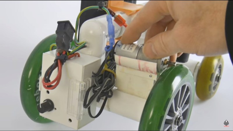
The are many ways to slow down a rotation. We’re assuming he was already at the minimum speed for the vehicle’s 8 RPM motor transmission and electronic speed controller. Gears or pulleys would probably be the next options. But [Eric] went even simpler, switching from roller blade wheels to larger diameter scooter wheels.
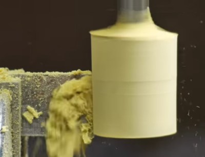
As simple as that sounds though, it led to that age-old conundrum, how to attach the wheels to the vehicle. The axle is made up of PVC tubes. So he machined square the ends of some PVC plugs and bolted the plugs to the wheel bearings. That left only to push the PVC plugs into the axle’s tubes. There are a number of ways he could have machined the PVC plugs, and the full explanation of the one he chose is best left to his video below. But basically, it involved first machining a Bondo body filler cylinder with a bolt embedded in it and then using the cylinder to hold onto the PVC plug while he machined that.
His solution for disengaging the motor is clever for its simplicity, made possible by the way the motor drives the wheel. The motor shaft simply applies pressure to the outer circumference of one of the wheels. Instead of fixing the motor permanently in place, he put it on a pivot so that it could be levered up, disengaging the shaft from contacting the wheel. At that point it’s easy to roll the dolly along by hand. Lowering the motor back down again reengages the shaft with the wheel. He uses a spring to keep the shaft pressing firmly on the wheel.
The result is smooth moving, professional looking footage.
We’ve seen a few variations of camera dollies here on Hackaday. That includes a sleek looking 3D printed one, and a programmable one great for doing time-lapse photography.


Considering he drives the wheels by friction on the outer edge of the wheel, the speed should be the same regardless of the wheel size.
Concur. The larger wheels will make any small bumps less jouncy, though, so this is still an upgrade.
Hmmm… I don’t know why I missed that, especially given all the pulley and gear ratio work I’ve done… or maybe that’s why. The tip came from Eric, the one who did the work and he said he changed the diameter to slow it down — that probably helped throw me too. He also said it was to improve the stability of the footage.
“…shaft simply applies pressure to the outer circumference…”
Bigger wheel, larger circumference, lower RPM, slower the dolly.
Lower RPM, but higher distance per rotation, so same overall speed.
RPM is lower, but linear travel speed over a surface is the same, because the reduced RPM is offset by reduced revolutions per unit of distance traveled.
Unless the old design had the motor driving the wheel somewhere other than at its circumference?
No, I checked the video, 2:11 is where he breaks down the original and it isn’t a hub drive, but an edge drive on the old smaller diameter motor.
Point made. The new dolly will go the same speed as the older version since as you say the linear distance traveled is the same.
Why does he have a hub the same diameter as the motor?
If he had the old wheel driving the new wheel it would have worked to slow down the speed.
No, that either wold have kept the same speed, or actually sped it up (depending on the exact arrangement). What would have slowed it down is sticking both old and new wheels on the same axle, contacting the ground with the small wheel, and contacting the motor with the large one. The motor experiences the same linear distance, but when you convert it to angular at the big wheel, and back to linear at the small wheel, you wind up with a much smaller linear distance.
To put it visually, imagine one rotation of the motor shaft. That one rotation is how far the shaft traverses the outer surface of the wheel. It’s also how much of the wheel’s outer surface traverses the table. That’ll be the same regardless of wheel diameter.
Thinking about the slower RPM is probably where my brain stopped until jpa’s comment made me facepalm.
Exactly. I had a motorized bike that spun a friction bushing on the rear tire and wheel diameter made no difference in speed at all. Seems counter intuitive until you really think about it.
The diameter of the driving wheel has actually no influence on the speed of the dolly. In this case only the diameter of the pulley on the motor shaft has.
Thou in the end it does what it is supposed to do…
One drawback of friction drive on a motor that is not speed regulated is the variable rolling friction along the outer diameter, which depends on how much pressure you apply, and any sort of dirt or dust, water, fingerprints, wear etc. so there can be slippage and variable load on the motor.
However, if friction drive is sufficient for the purpose, then you can modify the arrangement by placing the motor axis slightly off-angle which creates a drag drive continuously variable transmission. For example, placing the motor at 45 degrees to the wheels drops the output speed by half. That also cleans the wheel by pushing any dirt off to the side, but causes increased wear on the surface because it’s always slipping.
Another variation of the idea:
https://en.wikipedia.org/wiki/Friction_drive
Two discs rotating perpendicular to each other can make a CVT.
i am truly amazed at the replies above which show how gear ratios are not fully understood even though being a pretty basic concept.
+1
Are you saying the dolly should be moving slower given the larger wheel? We know the larger wheel is rotating slower, but it’s the dolly’s linear speed that was questioned.
Yes, gear ratios are a pretty simple concept. So is the fact that a large wheel rotating slowly will propel a vehicle at the same speed as a small wheel rotating faster, assuming that speed and size are adjusted in a linear inverse proportion. With this setup, that is guaranteed.
I haven’t been able to figure out why, but I find his videos to be nearly-unwatchable. Between minor technical errors, and his production style, it all just makes me uncomfortable to sit through.
I wish I had the sort of video production skills he clearly has – it’s all very impressive. But the final work isn’t for me, I think.
Neat video. If he put a disk over one of the wheels and had the motor friction drive the face of the disk, he could have built a fully variable transmission, and if the motor drive went past the center axis it would even be capable of going backwards. A few brands of riding lawn mowers used that dsign back in the day. Still it was a neat video. I had never thought about building a little rover out of PVC so I walked away with some ideas.
It is not that much of a hack but the result justifies everything, it is the coolest little camera dolly possible to make out of easily available bits. I wouldn’t bother with the machined wheel hubs, not having a lathe (sob, sob), but there are other ways to address that problem.
Get a Dremel (or similar, including some routers), a “duty cycle” AC control to change speed (the plain TRIAC type, you should use a ceiling-fan control unit since they’re inductive tolerant), use some angle strap to connect it to a board, and you have a light-duty lathe.
If you’re fine with a bit more work, buy a “bare” AC motor, fit it with a chuck of whatever design, and otherwise rig it like the Dremel above. If you already made the Dremel, maybe even use that as a tool mount.
If you’re fine with something you will never be able to move, and spending a few months to a year on the work, then look up the “Yeoman’s Lathe”.
Angle strap? I don’t even know what that is. Use metal strap, the sheet metal “ribbon” with pre-drilled holes in it.