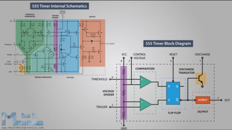
One way to understand how the 555 timer works and how to use it is by learning what the pins mean and what to connect to them. A far more enjoyable, and arguably a more useful way to learn is by looking at what’s going on inside during each of its modes of operation. [Dejan Nedelkovski] has put together just such a video where he walks through how the 555 timer IC works from the inside.
We especially like how he immediately removes the fear factor by first showing a schematic with all the individual components but then grouping them into what they make up: two comparators, a voltage divider, a flip-flop, a discharge transistor, and an output stage. Having lifted the internals to a higher level, he then walks through examples, with external components attached, for each of the three operating modes: bistable, monostable and astable. If you’re already familiar with the 555 then you’ll enjoy the trip down memory lane. If you’re not familiar with it, then you soon will be. Check out his video below.
This isn’t the only time we’ve toyed with the guts of this wonderful chip. A few years ago we were all delighted with this mega-sized discrete 555 kit and a little more recently, this teardown of the actual chip.


What?
There’s no Arduino inside????
How can people comment that a 555 could have been used instead of an Arduino????
B^)
I can’t wait until you explain how a Phase Lock IC works!
Pff. I could do that with a .Oh, sorry…
B^)
A 555 also makes a handy temperature stable schmitt-trigger with precisely set thresholds which you can change via the control pin, for when you’re having troubles making one with op-amps that latch up and refuse to co-operate.
In fact that’s exactly what a 555 is. You just provide feedback to make it into an oscillator/timer.
I first learned about the 555 while employed as a Signetics Field Sales Engineer around 1972-3. The complete timer series was being developed and I have what I believe to be the only 557s remaining and documents proving their existence. I also met Hans Camenzind who used the 555 timer with a modified metal layer to produce a custom chip that we used in our capacitance switches at Magic Dot that became the foundation for today’s LCD touch technology used in modern screens. The main innovation of the 555 IMO is that it bridged the digital logic families of the day limited to narrow DC V+ demands and the linear world allowing a more generous DC supply range. Hans’ design was brilliant because of this liberal supply range allowing this IC to become much more than just a timing circuit. BTW, if anyone has a data sheet for the 557, I would like to obtain a copy for posterity. Dave