Picture the scene: you’ve whipped up an amazing new gadget, your crowdfunding campaign has gone well, and you’ve got a couple hundred orders to fill. Having not quite hit the big time, you’re preparing to tackle the production largely yourself. Parts begin to flood in, and you’ve got tube after tube of ICs ready to populate your shiny new PCBs? After the third time, you’re sick and tired of fighting with those irksome little pins. Enter [Stuart] with the answer.
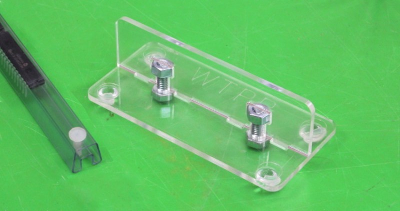
It’s a simple tool, attractively presented. Two pieces of laser cut acrylic are assembled in a perpendicular fashion, creating a vertical surface which can be used to press pins out of IC tubes. [Stuart]’s example has rubber feet, though we could easily see this built into a work surface as well.
The build highlights two universal truths. One, that laser cutters are capable of producing elegant, visually attractive items almost effortlessly, something we can’t say about the garden variety 3D printer. Secondly, all it takes is a few little jigs and tools to make any production process much easier. This is something that’s easy to see in the many factories all over the world – special single-purpose devices that make a weird, tricky task almost effortless.
In DIY production lines, testing is important too – so why not check out this home-spun test jig?


In the olden days we used to have to use a pair of dykes and just pop them out by hand. It was horrible.
Or a screwdriver, or your thumbnail, or a boxcutter, or…damn near anything but a custom laser cut acrylic waste of time.
I see this as putting in the work to make the process enjoyable, rather than a necessity to “get over with it”.
That would require several RGB neopixels to illuminate the acrylic, an Arduino to drive them, and another one to tweet about it each time you use the tool. And a tiny integrated robotic arm to flick the switch off on the whole thing when you’re done. Cynical? Who, me…?
I’ve used a claw hammer to pull them out like nails, seems to work okay.
The custom tool I eventually machined for changing Christmas light bulbs also works for this. There were literally a thousand of those though and that… hurt.
This is more like a solution in search of a problem. But hey… it’s a solution. Perhaps once you hit a hundred tubes..
Then again once you hit a hundred tubes you should probably just switch to surface mount.
Surface mount stuff comes in tubes too, sometimes.
doubt that in 100s… 10s – sure, but if you want a 100 or more, you’ll get a strip of cut tape :P
I’ve just looked, and the SMT tubes I’ve got have a rubber bung in the end rather than pins, so it’s all immaterial :-)
That’s way too late. I can not remember having un-pinned that much tubes, but I switched to SMD since quite some time.
So am I the only one that pulls them out with my teeth?
I’d be worried that all my co-workers were pulling it out with their teeth too.
I am the only one here with teeth so….
Nope. (Don’t tell my dentist.)
If you break a tooth, just 3D print a new one.
I was so confused…
I thought it was a device to push/bend the IC pins…
(So they would be easier to install in the pcbs)
I kept looking at the picture trying to figure out how it works. ;P
Same. It took ages for me to figure out they were talking about the plastic locking pin in the end of the tube.
Thank you pelrun! I was also stuck in the same blonde moment, but would have failed to grasp it had you not said!
Same here! I was smirking thinking of the comments above using their teeth to pull it (the IC’s) out of the board, or to bend the pins.
Same here… Couple hundred ICs? that’s going to be like 20 trays, do you really need a dedicated tool to push that pin out 20 times? If you do, maybe hand-assembling 200 PCBs is beyond your patience capabilities…
On the other hand, a tool to help get those ICs’ pins at the right angle for the boards will probably come in handy…
We used to use a tack puller like this one to pull the locking pins from tubes http://www.acehardware.com/product/index.jsp?productId=1288974&KPID=997565&cid=CAPLA:G:Shopping_-_Catch_All_-_DT&pla=pla_997565&k_clickid=694bc493-0b43-48e6-bfea-878e4b93be08&gclid=CjwKCAjws6jVBRBZEiwAkIfZ2mdr9wjX8OnD3uDPhuRK2xpOM07F7WLp6Q1S0oo3mYux6ZkPBZHvMRoC7fMQAvD_BwE
In the golden age of thru holes, there was a tool to bend the pins at right angle. Still got it by the way, along with the PLCC extractor.
Me too!
I did it always by carefully pressing the IC on the table from both sides. Not, that that was completely symmetrical every time :-)
Well yeah but by the time they were in the sockets nobody could tell… ;)
I too thought it were for bending the pins to the right angle, since they almost never are.
But I guess that a tool for removing the locking pin on the tube is a good idea too.
I myself use a pair of side cutters, or other similar tool. If it can’t be pulled out that way, then one can always cut it out.
That also was my preferred method. Like pulling any other nail.
Is acrylic considered a potential static issue?
untreated – definitely
But put a coat of something even remotely conductive on it and no need to worry. (unless it starts to wear/peel off)
OP was years ago?!?!
Insert a 6 where appropriate.
You’re right! Everything posted before (current date-3 years) is inadmissable for Hackaday. Editors are closing on my current position, I am not long for this world.
Are they? Woohoo, holiday in Australia on the firm! Lewin’s real hard to find, it’ll take me several months to search all those sun-kissed beaches.
On a serious note, as I understand Hackaday, we bring you cool stuff that interests us, and that we think will interest you. Even if it was done a few years ago, if it didn’t catch any attention in our community and we missed it at the time, if you our readers will like it then it’s worth featuring. It’s not often that something a few years old turns up, but it’s no less valid. I’ve certainly put one or two in, in my time.
well, lots of us are in Aus if you’re traveling.. :-) And I do have a holiday house at the beach.. :-)
We shall remember you fondly.
At the very least it will give us something else to whinge about :)
This took me an embarrassingly long time to figure out how it worked!
Well, I thought the way he used the bolts to hold the two pieces of acrylic together was pretty neat!
It’s called t-slot. Works fairly well, has a few limitations.
https://www.ponoko.com/blog/how-to-make/how-to-make-snug-joints-in-acrylic/
I noticed this morning that my NEJE laser engraver is held together the same way…
(Yawn!) Where’s the caffeine?
We get ours from Malaster. This thing could be easily 3d printed. They have had these for years.
http://www.malaster.com/products/our-product-lines/ic-tube-accessories/mc-1000pp-detail
Procrastination?
I was so good at crastinating, I turned Pro!
I use long and skinny cutter. Snip the pin and out they go.
I don’t get the fuss… I always used the table.
Place the chip on it’s side and gently press down and roll it against the table top to evenly bend all the pins straight. Be VERY careful when doing this or you could end up bending all the legs over flat. Once you’ve done one side do the same to the other.
But if you don’t have a table (or a piece of angled aluminum, which is very sturdy and has the correct angle directly from the shop) then an acrylic tool will do… though considering the effort it took to make a piece of angled acrylic, it would be nicer if it had the shape of a real IC-feet bender. Two slots that are slightly angled and force the legs into the proper angle just by sliding the IC along the slots.
oops… it’s is not about the pins of the IC… it’s about the pin in the tube. Sorry, silly me.
Well on that same table I have a model 170 Plato wire cutter… “snap” problem solved.
I’m surprised at the “negative” comments on this one. Well, I’m not to be honest, this is a comment section after all. He saw something that bugged him, he drew, cut out and assembled something in probably less than an hour or two that makes his life easier. What’s not to like?
The copywriting of the article and also original blog post explains this thing very poorly and many readers (including myself) were confused about what that thing do and how. I desperately tried to find some video or photo of it just to understand the main point which SHOULD have been clearly stated here. Thats why.
I know what an IC is, I know what those tubes are and have many, I know what pins are, I know what acrylic is, I know what a laser cutter is. I know everything about this thing except what the fuck it actually does which is not explained and is not obvious.
Put the groove of the tube on the acrylic upright , then push down on the tube , job done!
step 1. start the band saw
step 2. cut the tube(s)
step 3. don’t worry about ESD
thank you.
i should have stopped reading after [“you’ve whipped up an amazing new gadget, your crowdfunding campaign has gone well, and you’ve got a couple hundred orders to fill.”] (lesson learned.)
Hmmm i dont understand how ir works…..
Probably took longer to make the tool than to remove the plugs with side cutters.
For sure. Longest time needed to earn money for laser cutter :-)
Ohhhhh. Now I understand!
I too thought – great, something to do the pins on the ics! Sadly, not to be.
Well, I find putting the pins back in (if you can find them!) tougher than removing them…
Version 2.0 needs a lever.
They make a tool for removing those pins. I know because my boss bought one by mistake when looking for a different tool. When we finally figured out what the tool he bought actually did, we laughed.
https://www.thingiverse.com/thing:1705048
https://www.amazon.com/Great-Neck-TL4C-Tack-Lifter/dp/B00004Z2MI
The proper “tool” has existed for EONS. I met my wife in 1978 whose job it was to unpin tubes and test each chip on an Automated Fixture that was a joint solution between Tektronix and DEC (PDP-8E). She did it all day long. No, in those days, they didn’t use their front teeth…
When working manually with these chips in tubes it can be a bit irksome that the pins are too wide.
For single chips there are (pretty useless) pin aligners, but for somewhat larger batches a tool with a slot for the tube and two ball bearings on the side can push the side of the tube just far enough to align the pins of all the IC’s inside before you open the tube. Such a tool can save more time than the time you actually need to find the tool in some drawer somewhere.
For machine work you of course use SMD chips, much easier to work with.
Even for manual and low quantity PCB’s I prefer SMD. Drillling the holes, constantly turning a PCB to solder on the other side, components falling out while turning, getting confused by silk screen on the “other” side. Getting confused by constantly working with “mirror images”, trimming leads of resistors & capacitors. All those problems are all gone with SMD.
Through hole is only nice for projects which do not have a dedicated PCB such as working on Breadboards or single quantity / veroboard projects.
…on the other hand through hole gives you proper mechanical robustness for those components that need it and free double-sided connectivity if you can’t afford to spend your kids college fund on PCBs or wait months to receive them from China.
Take a cheap/abused flat bladed screwdriver and grind a small notch into the middle of the blade, then bend the end upwards a bit. Now you have a pin-scale crowbar tool. Some Craftsman screwdriver sets even have a “screwdriver” like this.
Most of my parts tubes (both SMD and TH) have a pin driven at ONE end, and a rubber/silicone stopper in the other end. No tool necessary to remove the stopper.
If I were to do make the tool described here, I’d at least put a small divot in the top edge of the vertical piece so that the bottom of the pin naturally rests someplace.
Time to upgrade to SMD though.
Back in the days of DIP ICs, there was at least one chip maker that made a gadget to remove the tube stop-pins. They even made a fancy advert for it — I think it was called a NailSaver, or something like that. Does anyone else remember it? Which chip maker was it? Nat Semi? Does anyone still have one?
Just use shears to cut off the end of the tube that contains the pin (assuming that you’re not going to reuse it, or don’t want to use tape). No flying pins to poke you in the eye.