
When they need to add temperature control to a project, many hackers reach for a K-type thermocouple for their high-temperature needs, or an integrated temperature-sensing IC when it doesn’t get that hot. The thermocouple relies on very small currents and extremely high gain, and you pretty much need a dedicated IC to read it, which can be expensive. The ICs aren’t as expensive, but they’re basically limited to boiling water. What do you do if you want to control a reflow oven?
There’s a cheaper way that spans a range between Antarctic winter and molten solder, and you’ve probably already got the parts on your shelf. Even if you don’t, it’s only going to run you an extra two cents, assuming that you’ve already got a microcontroller with an ADC in your project. The BOM: a plain-vanilla diode and a resistor.

I’ve been using diodes as temperature sensors in three projects over the last year: one is a coffee roaster that brings the beans up to 220 °C in hot air, another is a reflow hotplate that tops out around 210 °C, and the third is a toner-transfer iron that holds a very stable 130 °C. In all of these cases, I don’t really care about the actual numerical value of the temperature — all that matters is reproducibility — so I never bothered to calibrate anything. I thought I’d do it right for Hackaday, and try to push the humble diode to its limits for science.
What resulted was a PCB fire, test circuits desoldering themselves above 190 °C, temperature probes coming loose, and finally a broken ramekin and 200 °C peanut oil all over my desk. Fun times! On the other hand, I managed to get out enough data to calibrate some diodes, and the results are fantastic. The circuits under test included both best practices and the easiest thing that could possibly work, and the results are pretty close. This is definitely a technique that you want to have under your belt for most temperature ranges. The devil is in the details, of course, so read on!
Diodes
We all know what the forward voltage drop of a run-of-the-mill silicon diode is, right? 0.6 V or 0.7 V or so, and that’s good enough for a lot of napkin-based calculations. But this voltage drop depends on two main factors: the current that you’re driving through the diode, and the temperature. If you hold the current fixed and read the forward voltage, you’ve got yourself a temperature sensor. While it can vary a little across diodes, figure on a response of -2 mV/°C.
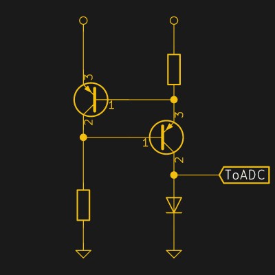
Holding the current “fixed” can be as simple as using a resistor: because the diode’s forward voltage doesn’t change all that much, the current through the resistor is almost constant. All you have to do is settle on a suitable resistor value. The next step up is to build a constant-current supply out of two transistors. I test out both of these methods here.
This isn’t news, though. The next step up in complexity, used by most of the IC temperature-sensing chips, is the “silicon bandgap temperature sensor“. Instead of a diode, two transistors are used, and common-mode imperfections are cancelled out with an op-amp. This works great in an IC, where the two transistors can be nearly identical and at the same temperature, but for DIY purposes, it adds more complexity than it’s worth. Here’s a white paper if you want to dig into the details.
Instead of aiming for accuracy that’s measured in fractions of a degree, however, I’m interested in ballparking how accurate the simplest homemade hacker solutions can be. What do you gain by adding in a real constant-current source? Is it worth it? Let’s find out.
Experimental Design
I took seven diodes, six 1N4148s and a 1N4002, and heated them up along with a K-type thermocouple and a pretty good Fluke multimeter that reads it. The 1N4148 is a dead-standard small-signal diode, and it comes in a non-melty glass case: it’s perfect for our purposes. Three of the 1N4148s were supplied current through a 10 kΩ resistor, simply because that’s a good middle value and I wanted to assess the diode-to-diode variability. Two other resistor values were chosen, 3.3 kΩ and 100 kΩ, roughly spanning the reasonable range of currents.
I paired the 1N4002, a high-voltage, high-current rectifier diode, with a 10 kΩ resistor to see what effect a different diode type had. Finally, the last 1N4148 was driven by a constant current circuit, straight out of Art of Electronics, that supplied a pretty solid 50 μA.
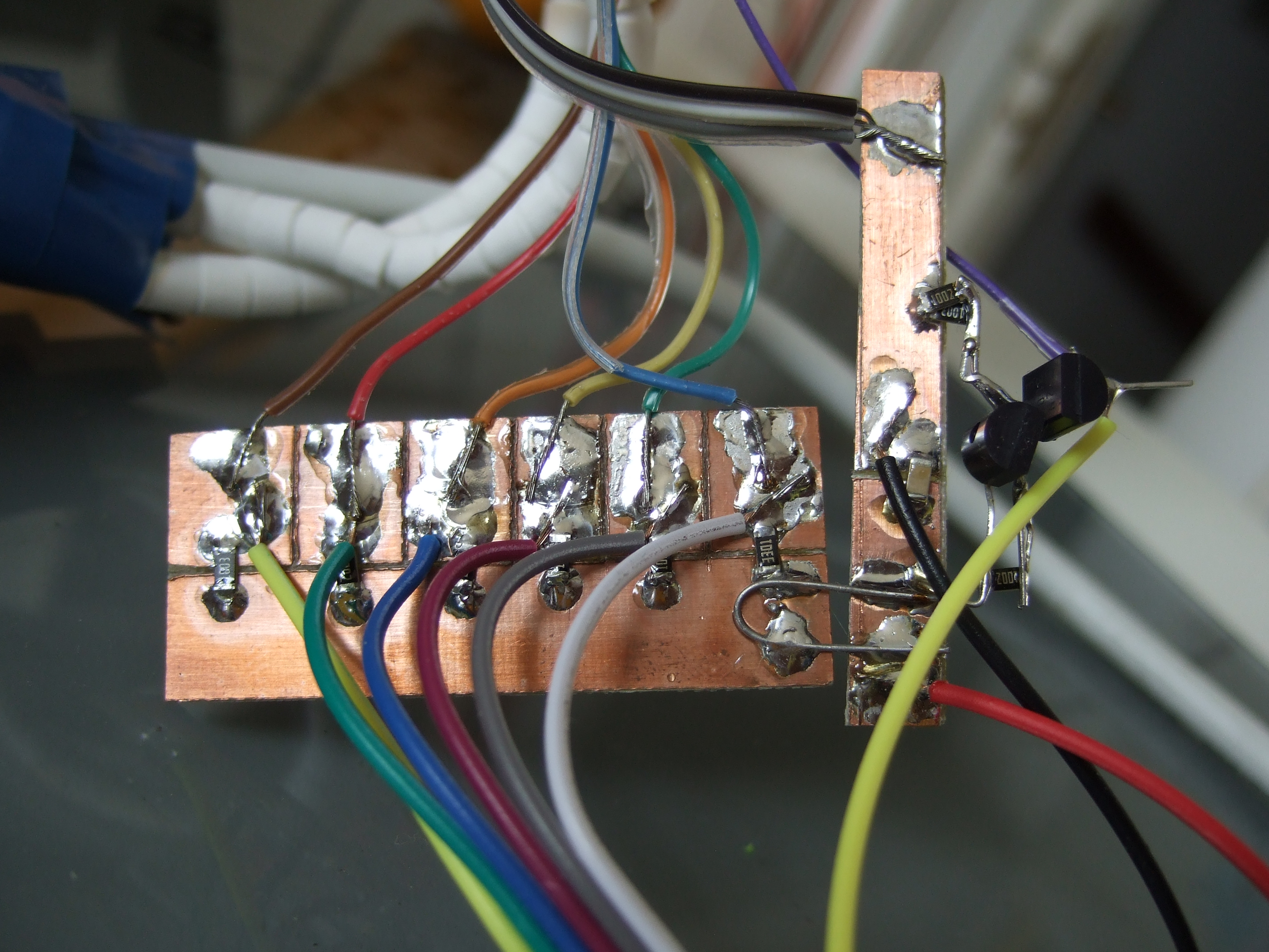
An STM32 microcontroller was programmed to take readings from each of the diodes whenever I typed in a temperature. If I had a logging multimeter, this could have been a lot less boring. As it was, I waited for the displayed reference temperature to hit an even five-degree value and typed that in to the STM32, which read out the seven ADCs and printed all of these values over the serial port. So I’d heat all the diodes up, log the data on my laptop as they slowly cool, clean it up once it was done, and graph it.
Sounds easy, right? Well, here’s where it gets fun. The real trick is making sure that all seven diodes and a thermocouple are at the same temperature, ranging from room temperature all the way up to burning-PCB.
Four Fails Equal a Success
Talking with Hackaday’s own Mike Szczys, he asked how you solder diodes when the temperature exceeds solder’s melting point. I naturally replied that I always crimp in those situations (which is true) and then went on to build a diode test rig with soldered connections. Having read somewhere that peanut oil is good up to 210 °C or so, I thought it would make a great immersion medium to even the temperatures out. Well, that it did, because all of the solder joints came undone at the same time at 190 °C: a great test of temperature uniformity. This was also a valuable calibration of my reference temperature probe — the melting point of 60/40 solder is 185 °C – 190 °C. Spot on! But no data is logged when the wires come unsoldered.
When I reflow, I use a hotplate with a (crimped) diode as a temperature sensor, but I’ll often Kapton-tape another diode or two to the PCB in question to get an on-PCB measure. And because the legs of these diodes are dangling in the breeze, I’ve gotten away with solder joints. So I figured that would work here too, so I resoldered the test rig with seven new diodes taped to a piece of blank PCB to equalize the temperature. Everything looked to be going until just below my target temperature of 250 °C, when I smelled smoke. I turned off the heater immediately and started logging temperatures, and sure enough they went down. And then they started to rise again, and there was a lot more smoke.
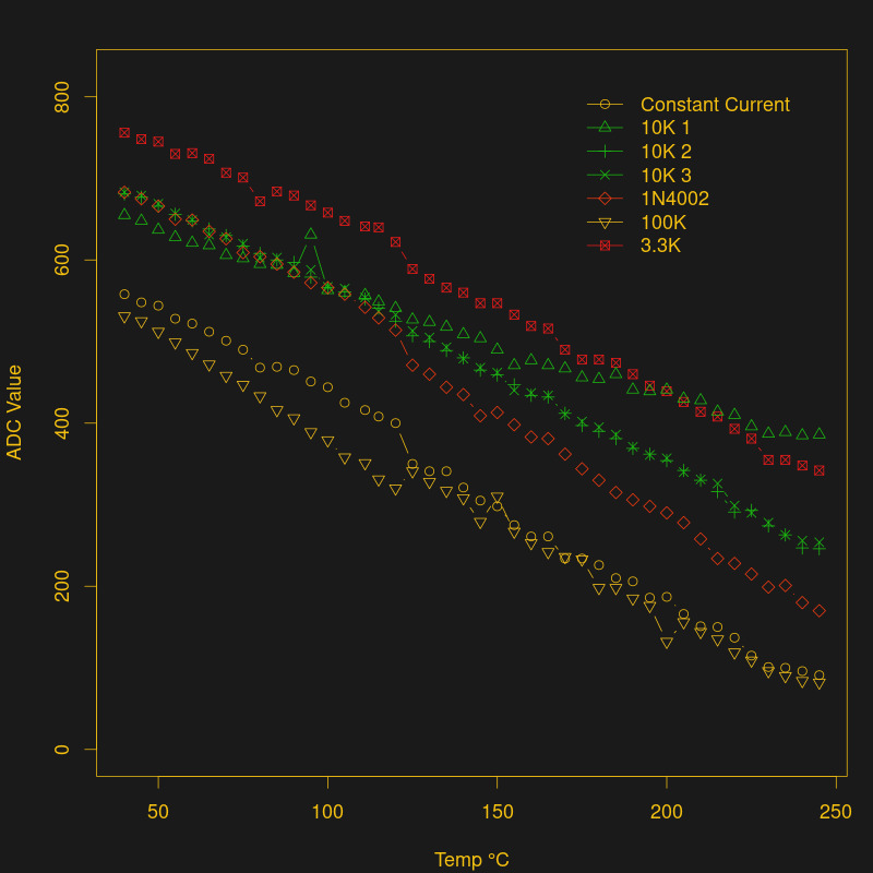 The epoxy layer of the PCB was on fire! It turns out that it’ll start to smolder at about 240 °C and burns nicely at 260 °C. Instead of going for the fire extinguisher, I opened some windows, kept on logging, and took out a camera. I actually got some data out of the run, but my office still smells a bit.
The next fail involved taping the diodes directly to a solid metal plate. It wouldn’t burn at 250 °C, after all. The problem is that it cools down very slowly unless you remove it from the ceramic heating element, and in the process the diodes and thermocouple wiggled themselves loose from the plate, resulting in an anomalous five-degree drop in temperature across the board. It turns out that this happened to a lesser extent in the firey-PCB run as well. You could work this out with some data massaging in post-production, but I decided to give the hot oil treatment another chance because it solved the contact problem very nicely.
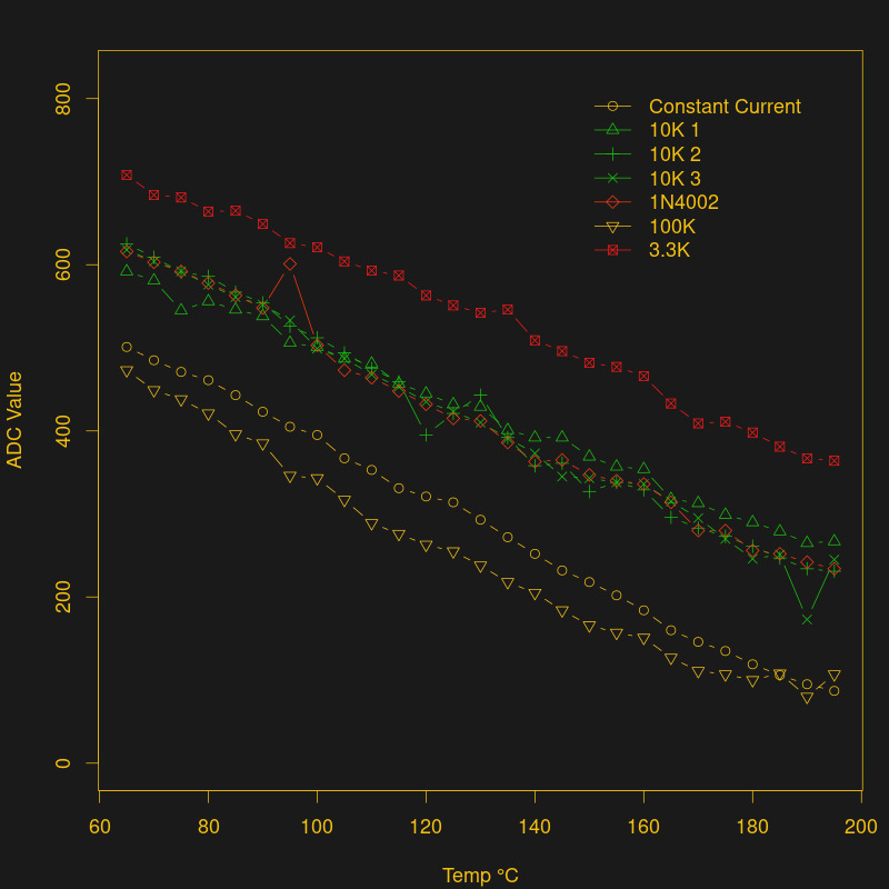 The final run was with peanut oil again, but this time starting from a mellower high temperature of around 200 °C and without fully immersing the solder joints. And it would have worked too, if it weren’t for the ramekin cracking as it hit the slab of marble that I used to cool it down. In retrospect, this was obvious, and it probably would have worked flawlessly if I put in on a silicone hot-pad. With 200 °C oil leaking out all over my desk, and copious amounts of paper towel, I managed to log this run, at least until the oil was all gone. I’ll clean up tomorrow.
The final tally: two useable datasets, one from the burnt-PCB run and one from the cracked-pot oil immersion test. Nothing’s perfect, but it’s enough to draw some conclusions.
Results
My first conclusion is that the simplest method of all, a diode and a 10 kΩ resistor fed into an ADC, is sufficient for non-precise work across any reasonable temperature range. I knew this from using it to reflow solder and roast coffee, but I was still impressed by the good linearity of the diode when compared to the thermocouple reference. You should be using this “trick”.
Next, building a constant current source is probably not worth it unless you really care about nailing the temperature. If simple reproducibility will do, don’t bother. Yes, I got absolutely beautiful results out to 220 °C, but the difference between the best and worst cases is probably one or two degrees across the range. You should spend your time on ensuring good physical contact between the diode and the object that you’re measuring first, and then wire up transistors second.
The 1N4002, a big, beefy diode, performed nearly identically to the 1N4148 when fed with the same resistance, and the three 1N4148s tracked each other perfectly. The only thing that matters is the current. Honestly, I was surprised. This suggests that you could simply buy a bag of diodes and 1% resistors, maybe calibrate a few to verify, and you’re done. Since the slopes of all the diodes are nearly identical, you could even calibrate them with one point at room temperature. How easy is that?
Want to know what’s actually hard in all of this? Testing the circuit outside of the range at which it’ll function.
[wpvideo 4tPzJeY3]


Really great read, thanks Elliot!
“I could do that with just a 555-timer!!”
After looking at a 555 internal schematic, it looks like pin 2 to ground will work as a diode.
So yes, you can do it with a 555.
So, now I know what a ramekin is.
Good one well executed…one of the best articles in a while!
I thought the constant current circuit source shown was susceptible to thermal runaway?
Specifically, the resistance of the junctions in the transistors go up with temperature, so the current goes down, so the circuit adjusts to supply more current, which causes the temperature to go up even further.
I once worked on a project where the engineer tried these circuits and had that exact response.
Is that no longer a problem with the current mirror?
That’s possible! I was running it at around 50 uA, so there’s not gonna be any thermal anything going on. Remember, we’re trying to just forward-bias a diode, so any extra is “wasted”.
I do not agree about the “not gonna be any thermal anything going on”.
The PN junctions in the tranistors have the same temperature characteristic as the PN junctions jused as temperature sensors.
Good luck if you want to use a diode & current source with that for example for a room thermostat where everything has the same temperature.
Just the diode and a resistor (from a temperature independent voltage source) is probably better. You will loose a bit of linearity, but it is inherently non-lineair anyway https://en.wikipedia.org/wiki/Diode#Shockley_diode_equation
And an STM32 has plenty of horses to compensate for that.
At higher currents that might be a problem. I didn’t see the supply voltage specified but an STM32 probably means 3.3V, so with the lowest bias resistor of 3.3kOhm that would be 1mA. So worst case dropping 3.3V at 1mA give 3.3mW, well within the 500mW for even a 2n2222
The resistor above the PNP on the right keeps thermal runaway from happening.
Any current flowing through the PNP on the right has to flow through the resistor, and for small changes, the voltage across the resistor changes about 40x faster than the transistor’s base-emitter voltage. The increasing voltage across the resistor pushes the PNP’s emitter voltage down, reducing Vbe and shutting the PNP off.
The PNP on the left doubles down on that, since its Vbe is the same as the voltage across the uper-right resistor.
As the voltage across the upper-right resistor increases, Vbe for the PNP on the left does too, turning that transistor on harder. That sends more current through the resistor to GND, increasing the voltage across that. The resistor to GND controls the right PNP’s base voltage, so that will rise too. With its emitter voltage falling and its base voltage rising, the PNP on the right has to shut down.
Just increasing the temperature of the PNP on the left would also tend to shut down the PNP on the right, since the additional current through the PNP on the left would still raise the base voltage for the PNP on the right.
The exact amount of current through the PNPs does change with temperature, but not enough to create a positive feedback loop and trigger thermal runaway.
You can improve the circuit’s performance by adding a second resistor on the left, so the right PNP’s base is connected to the middle of a voltage divider.
If you choose the value of the divider’s upper resistor so its voltage drop is about 26mV (the thermal voltage for a BJT), small changes in current will approximately cancel any changes to Vbe for the PNP on the right. It’s called a ‘peaking current source’ since the current proportional to temperature rises to a maximum level then starts to drop off again.
Isn’t the max junction temperature usually 175 deg. C? I once saw a clever circuit that ran two different currents through a remote temperature sensing diode and calculated the voltage drop due to wire resistance (linear with temperature and current) and due to the diode (non-linear with temperature and current).
It’s supposed to stop being useful around 250 °C as some other effect takes over. I was trying hard to get into this nonlinear region, but stuff kept burning up. :)
I think you can see a little bit of the knee in the scorched-PCB run, actually. But with one or two data points at that temperature range, and the fact that I’ll freely admit to being a tiny bit distracted, I wasn’t going to oversell it.
They’re certainly linear enough for my purposes (+/- 2 °C?) up to 220.
There are chips like the TMP513 that allow the use of diode connected transistors as remarkably accurate temperature sensors. And using different currents to adjust for wiring resistance is just one of the tricks used.
Was there any data going in the other direction. Say down to freezing point? This would make some nice cheap replacements to 1 wire sensors where accuracy doesn’t matter :D
Freezing point of water is no issue, freezing point of nitrogen could be a problem. :-)
I know of experiments from CPU overclocking: Some brands did not boot up at liquid nitrogen temps, but so basic components like a diode will not have electrical problems at this temp. Thermal stress in the casing could be a problem, I don’t know if glass or plastic housing would be better.
I use 2n2222 base emitter junctions down to 77 Kelvin ( -230 F ) .
They are good to withing 1 degree of $450 purpose built temp sensor diodes. Good enough for me.
Hm, 77 Kelvin or -230° F is 50° C apart in my physics… so, this wouldn’t be accurate enough for my requirements! ;) Would be interested to learn for what you use those, too.
77 Kelvin is -321F so my hunch is that the “-230” was meant to be “-320”.
I deal a lot with temperature sensors. It bothers me that 99.99% of the temperature sensing projects and articles are about HOT temperatures. No body deals with Cold temps. which are IMO harder to read.
-80C or -196C , these things are challenges.
The first Arduino powered thermometer I built was with a diode. I calibrated it with a hot block at work set at 100c and with ice water. Then I tested it out with dry ice. It matched the stated sublimation temperature of dry ice to the degree… So it works well at low temps, at least until you get around 5-10 Kelvin….
Hm, 77 Kelvin or -230° F is 50° C apart in my physics… so, this wouldn’t be accurate enough for my requirements! ;) Would be interested to learn for what you use those, too.
After some failed attempts this reply ended up at the wrong place. Sorry about that.
Getting down to below -80C I’d say is a lot harder for the home hacker than heating things up. Also most of the projects involving low temperatures that this sort of community would be interested in would suffice with temps no lower than dry ice. As dry ice sublimates at -78.5C I’d conclude then that there are very few hackers going below that and thus you end up very few articles on the matter.
If you are bothered enough then you could take the opportunity to capitalise on the lack of low temp hacked thermometer articles and write your own. It sounds like you have the necessary background knowledge.
I’d like to see if a home made hydrogen filled Stirling engine run in reverse would be useful for such low temp projects.
I just saw a Ben Heck video of using a (something from a cell tower?) to collect liquid nitrogen from air.
It was a bit involved, so going down to H2 would probably be harder.
Unless you mean burning the hydrogen to get the Stirling to work!
B^)
The hydrogen would be used as the heat transfer medium. I suppose you could use it as a fuel too :) It improves the efficiency of the engine and is cheaper than helium, through a little less safe. It also won’t liquefy at any temperature I can envision needing, for example superconductors, infrared cameras, cryosorption vacuum pumps.
Yeah generating such cold temps can be hard. I have about 10 devices out on the field at -80C some up to 3 years old… but it took a lot of effort to get it right and in some cases it still is. Just saying, I would like others to suffer what i have and read about it to learn.
On the link below you can find my Low temperature contribution to the driver on my compilers forum.
https://www.ccsinfo.com/forum/viewtopic.php?t=49599&highlight=
I do try to give back from time to time.
Dry ice
I think it’s because electronics geeks are generally more interested in heating stuff like solder, printer nozzles… and coffee
OTOH, cooling processor chips (liquid/peltier/vortex/etc, freeze spray in troubleshooting, IR imaging, kegerators!
I hadn’t even thought about the colder direction. (Which is a lot like saying, “you’re right!”) What are the challenges, and why? Point me to enough interesting resources and I’ll have a look.
Most of the stuff I deal with is with Medical Freezers and/or Biological Samples (think Fertility).
I’ve had success with Thermocouples and RTDs to -80C, limiting myself to things known to work reliably.
(thermcouples where a bit tricky i must admit)
The RTD although capable of going to -200C, the cable material or insulation will most likely deteriorate or crystallize.
Most “hacker friendly” devices and/or breakout boards have a lower limit of about -40C. I tried some Thermocouple Specific IC’s and found the datasheets full of promises and shortly after an errata detailing the lack of accuracy.
Ive pushed DS18B20 to -25C reliably – I have one in operation for 3 or 4 years now, not a single problem.
But this is close to the lower limit of the device, and haven’t tried to go lower because i don’t want to risk the sensor working for 2 weeks and crapping out Right when it matters.
Linearity is a big problem or needing high gain amplifiers because the votages/changes are so small.
And as said before, the insulation marterials are also an issue, like for the cables or water proof bulb.
I could take the 200 – 700 dollar route for Silicon Cryogenic sensors but that no fun.
Ive been thinking of trying out diodes as you did in this article, which is why i enjoyed reading it.
oh… and obviously Cost is a challenge.
Thanks a lot for this view. In my work, I might in the future need to go down to those temperatures. Currently, I’m at a minimum of -10C, which is still rather easy to do.
Why were the thermocouples so tricky at low temperatures? Do they generate a voltage too small to amplify?
No, just the sign changes. They generate a voltage proportional to the difference. But probably some 0 point compensation chips get a problem.
As I mentioned in an earlier post.
I use Lakeshore DT-670 diodes that cost on the order of $450 – $650 and are good down to well below 77K with uncalibrated accuracies of the order .1K. And I do use these. But for general use I use a 2n2222 or PN2222.
They read out exactly the same way, but may have offsets of +/- 1 to 1.5K. at room or Liquid Nitrogen temperatures.
But they cost $0.25 each, so I use them freely around instrumentation for general monitoring.
I don’t remember how far down they go but I think they still work at 20K.
By 4K the carriers may have started to freeze out.
I know they dont work at 1.5K.
None the less for Hackers, just use 2n2222s.. if you need the absolute cal, just get the offset at room temp and you will be within .5K easily.
Cheers
Kevin
For low temperatures (and relatively low precision demands), use a simple carbon resistor. At my work, I used such a simple analog gauge with a display going down to 4 K. The small resistance dependence on temperature was detected by a common H-bridge.
It’s squirrelly using the forward voltage of a diode to make accurate temperature measurements. The variation from one part to the next makes the error pretty large, unless you calibrate each one.
What works very well, however, is the delta Vbe method. This measures the difference in Vbe of a transistor at two different collector currents. You can do this using a microcontroller, and there are chips (e.g. LM86) that do it directly. You can get 1 deg C accuracy from a random 2N2222 using this method.
For more info, see “Transistor Sensor Needs No Compensation,” Jim Williams, EDN Magazine, April 25, 1991.
You Sir deserve an upvote! That’s the true poor man’s method of accurate temperature sensing!
Are those “old” issue available somewhere? Can’t find this article anywhere?
Cool idea. I ended up finding the circuit in this app note on page 7.
You could very easily do the same thing with the diode — just switching between two constant currents and measure the difference in voltage. (After all, his circuit is just using a diode-connected transistor for the same junction.) You’d have to redesign the current supply to put it under microcontroller control, though.
That said, I didn’t see much of a difference between the six 1N4148s and two 1N4002s that I ended up testing. I was shocked by how consistent they were, because I’ve heard a lot about their variability.
Strangely enough, the solution to the current supply redesign is right there in the same document. Page 5.
I’ve read that diode-connected transistors are supposed to be better for temperature sensing. Haven’t seen a good explanation of why, so I have been meaning to try it.
Diode-connected transistors are really just skipping over one part of a PNP / NPN sandwich and getting you to a PN junction, so from a bird’s eye view, there’s not much difference.
But there’s a lot of detail in the construction of the junctions inside a transistor, and nothing’s as symmetric as it would seem in the physics textbooks, so maybe!
My understanding for this was that there is a lot more care and quality control in fabricating transistors than diodes, as a specific part number of transistor, e.g. a 2N2222 should behave like a 2N2222 regardless of what batch it came from, and this necessitates a bit more care in fabrication, as a transistor has a lot more characteristics that need to be right in order for it to work properly… At least this is what I was given as a response when looking into this question. YMMV.
Diodes like the 1N4148 are a Small Signal “Switching” device so there is limited design consideration for linearity of the forward voltage (Vf) vs forward current (If) characteristics.
There are also Small Signal “Switching” transistors and they would behave much like the above diode.
However most common bipolar transistors are “amplifiers” and for these much greater design consideration is given to the linearity of Collector Current (Ic) being a linear product of (Gain) Hfe and Base Current (Vbe). In order to achieve this there needs to be more linearity of the relationship between Ibe and Vbe.
Base Current (
VbeIbe)I didn’t see if you mentioned the source of your diodes. Diodes from the same lot are likely to be similar. Diodes from different vendors, or pulled from random old gear, might show a larger difference. Nice post regardless.
All the 4148s were from the same bag, but the 4002s were out of my junk pile — probably came in a random assortment of diodes from a surplus store a decade ago.
Nothing old about this. Majority of modern temperature sensor on silicon do this still. Or a variation. I had a colleague use 5 currents in a specific ratio to get highly accurate temperature sensors
“It’s squirrelly using the forward voltage of a diode to make accurate temperature measurements. The variation from one part to the next makes the error pretty large, unless you calibrate each one.”
From the article:
“The 1N4002, a big, beefy diode, performed nearly identically to the 1N4148 when fed with the same resistance, and the three 1N4148s tracked each other perfectly. The only thing that matters is the current. Honestly, I was surprised. This suggests that you could simply buy a bag of diodes and 1% resistors, maybe calibrate a few to verify, and you’re done. Since the slopes of all the diodes are nearly identical, you could even calibrate them with one point at room temperature. How easy is that?”
Very cool. Thanks for that. I had not seen that trick before! Lots of good reading today :)
“Don’t try this at home… Better burn your office instead.”
Enjoyed reading it!
Or one could just use a dedicated ntc or ptc for 10 Cents per piece
Indeed, that’s what he nearly did comparing it with a resistor. Im sure this is more to get every one thinking than anything else!
I have also seen diodes used as level detectors for LN2 dewars.
Nicely done. This reminds me of my old EE lab back in college. There’s no absolute single solution to solve all problems. This is one of the quick and easy way to implement a temperature sensing feature into your projects. As long as it fits the requirements of what you need to accomplish, there’s no point of over designing something. Really appreciate your detailed write up here. Thanks!
Come on Elliot, you can tell everyone you used Mecrisp-Stellaris Forth with a ‘Temperature’ Word to take those readings ;-)
Excellent article, really timely and you’ve inspired me to do the same for a hotplate re flow device I’m making.
As a side note, back in the mid 80’s I made up a oil bath for calibrating temperature gauges and I used a string of four 2N3055 power transistors as the heating element suspended within the oil bath itself. I discovered that at about 230C they would suddenly die, and a autopsy revealed the big lump of silicon inside these NPN power transistors was now a melted puddle.
Cheers,
Terry
LOL. Touché:
adc-init

\ need to init 7 ADC channels -- put 'em in a row

: init-adcs 7 0 do i i adc-pin-setup loop ;

init-adcs
: read 7 0 do i adc-set-channel adc-once . space loop ;
: get-temp cr ." temp: " pad 4 accept pad swap evaluate ;
: print-temp 0 type ;
: header cr cr ." data R3.3k R10k1 R10k2 R10k3 R10k4007 R100k constant temp " cr ;
: cycle begin get-temp dup 0= not while cr ." data " read print-temp cr repeat ;
: go header cycle ;
That’s the whole thing. Type “go” and it prints out the header for the .csv file and starts logging with every temperature input.
I have it print out “data” on any line that I want to keep in the logs so that they’re easy to filter out. Then
sed -n '/data/p'to print the data lines, andsed 's/data //'to get rid of the word “data”.Slick! I wonder what your pad Word is as I’m trying to understand your get-temp. Strong your String-Fu is …
The reason I made the oil bath was so I could calibrate a number of temperature sensors and get them within 0.5C of each other as this is very hard to do as you have observed. I stirred the oil manually but something automatic would have been nice. One advantage is that oil is non conductive so the sensors don’t have to be insulated etc.
Heya. Oh sorry. I trimmed that word out b/c I didn’t know I was using it… I shouldn’t cut/paste code in comments, instead just link to the file. But I thought I could get away with it…
Pad is just a buffer for input text.
10 buffer: padSome Forths come with one natively. 10 characters is plenty, I was only using 4.The string stuff boggled my mind for quite a while. Forth has no “a2int” or similar, b/c it doesn’t need one.
evaluate, which is used in the command-line interface, does the work for you already. (It also can run arbitrary code, naturally.)The first half of
get-tempis just creating a prompt. The rest,pad 4 accept pad swap evaluate, uses accept to read in up to four characters — it leaves the actual number read (not including CR) on the stack. You could doswap typeto print it right back out, but instead,swap evaluate“runs” the input. And since the ascii representation of numbers evaluates to a number…Yeah. That took me 1/2 hour to come up with, once upon a time. One of the odd challenges of using Forth is coding without Stack Overflow, or heck, any good code examples. It’s silly, but I like it.
I built a temp controller for a pace desoldering station and used a ceramic diode for the sense element. I am thinking this was around 1979, and it was old news when I did it.
No mentioning of the LM35? It’s a transistor housed laser trimmed amplified version of the diode that give a 1mV/0.1C calibrated output. costs a Dollar.
And its Imperial sibling, the LM34, also nice because you can get them in hermetic metal can packages that can be thermally bonded to metal stuff you need to measure. I use them all the time.
You know, THIS is the sort of content that is really, really unique and worth making HAD a daily/hourly(?) read.
Would be a fantastic write-up if someone where to comb through the archives and gather all of these misc. ‘cheapie’ solutions to unique and not so unique problems.
Probably draw far more new visitors by word of mouth than yet another 3-d printer, or Arduino-blinky post.
Agreed. Even brief articles on rare-gem quality sources like this one linked in an above comment would be of enormous value.
We aim to please! Stoked you folks enjoyed. Pieces like this are super fun to write, too.
Thermocouple amplifiers are really not that difficult to make. A modern micro makes the cold junction compensation a case of subtraction. And it’s not the currents that are low, it’s the voltages. If memory serves, a K type Thermocouple has a voltage of 41 micro volts per degree Celsius there are a lot of op amps that provide offset variation per degree Celsius of well under 10 micro volts per degree Celsius. I’ve even used a simple lm358 is designs measuring temperatures of upto 1000 degrees. Not to worried about single degrees here.
Don’t discount thermocouples, go play, and to make sensors, I have even simply passed exposed ends of K type cable through the arc of a welder. Quick, simple, cheap, low inertia, but not isolated. Good if you quickly need to hack a sensor together.
Thank you again Elliot! I have a partially disassembled air popper in the workshop right now thanks to your last article. You are an asset to hackaday and they should give you a raise based on article quality!
Ok… One of your last articles.
One of his last articles? Can someone explain ?
I think he meant “latest”, not “last”
Replace “last” with “most recent” and it makes more sense. Not “last” as in “final”.
To whom do we send the Sympathy cards?
i am so mad at you for burning a pcb indoors
I’ve often used a 1N4148 as a temp sensor and there fine for an accuracy of +- 2 deg C. I think the 1N914 has a different temp range.
Some other tips.
You can do the same with the Base – Emitter junction of a bipolar transistor. This has the added convince of easy mounting with TO-220 TO-3 TOP3 case outlines.
You can also use the same transistor as the heating element for low power applications. 2 uC pins – 1 through a resistor (can be digital or PWM) to drive the transistor and 1 analog input connected to the Base to read the temp. You need to calculate a Collector load resistor to suit the max current and power of the transistor given the supply voltage. Screw down high power wire wound resistors are good for this.
The drop across a silicon PN junction varies with temp – that’s what this is all about – people are measuring the Vf forward junction voltage of diodes with their meter which has a very low forward current and this does not accurately reflect what the Vf would be in-circuit. A 1N4148 is a small signal switching diode and is designed for very low currents so 0.6 Volt is a good ball park figure for it’s in-circuit Vf.
By the time you get to a 1N5404 you would expect an in-circuit current of 1 to 2.5 Amps where Vf is closer to 0.4Volts.
Also your favorite AVR probably has an internal 2.5 Volt analog reference which will increase the scale of your analog readings. It’s just a register setting so it can be switched in and out on the fly.
Great tips on the transistor side! I like the heater / sensor combo idea.
Some chips (some AVRs too) have a 1.024 V reference, which would be even better as long as you’re only measuring hot. I was using an STM32 at 3.3 V — I probably could have done better — but it’s got a 12-bit ADC, so I didn’t sweat it.
Also note: I didn’t do any smoothing/averaging in the temp sensing. I just took one ADC reading and believed it. I almost never do this in practice, though, b/c you can get easily a few more bits of resolution by averaging a noisy, slow measurements like this.
Couple random thoughts; Versus wire crimps, plastic wire nuts but crush the plastic to get the taper-spiral spring inside. Avocado oil, good to 500 F. (I have switched to it for any hot oil cooking.)
500 only sounds high in F. Actually it’s 260°C, very similar to the 250°C from the article.
Well, I’m not eating what YOU cook… ????
My wife and I have also switched to avocado oil for just about everything except oven roasting vegetables. Nice high smoke point without the addition of flavor or digestive issues (eg grapeseed). Plus it’s great for keto!
Yup. All I use, now, too. For you turkey fryers of the peanut oil ilk, avo goes to 500F, more than peanut oil. I don’t touch canola, willingly. Hot topic, eh?
And now for the back.
Take two one cent coins of different compositions and make a thermocouple :D
Well all modern US 1 cent coins are composites. It’s before 1981 or 1982 where you get the copper pennies.
I wonder what kind of sensor you would get from soldering two wires to a modern penny(after using file to get below the copper outer on one side)? Have to try it some time, it’s not like a penny costs all that much..:)
More diode details:
https://web.archive.org/web/20160105011327/http://www.cliftonlaboratories.com/1n400x_diode_family_forward_voltage.htm
Anyone else have an odd bug occur with the video player on this page? I just submitted a bug report for Chrome (Android) for it. My screen rotation was disabled, but when I played the video at the bottom of the article the player forced landscape + fullscreen. Then wouldn’t let me back into portrait mode! I could rotate 180° to the other landscape but neither portrait mode. Other apps and the OS were unaffected. Switching in and out of chrome did not remove the issue; I had to kill the app to restore normal behavior.
Mayyyybe, the best article&comments, (a pkg deal,) I had had the pleasue in HAD, despite loving many topics. No bickering. All comments V mannerly, in the V best style of commaraderie. I am sad this is not a book that allows me to take these overviews to subsequent chapters and truely understand, but I am retired & sans a degree or prolific energy. It’s a (very pleasant,) struggle to try to create a shunt Vreg for VJMC’s of the 60’s… but tidbits here, have helped. No more engr’g pals left in sillycom valley. Even the Ampex Sign, threatened. What can one do? Carry on, lads!
Those forward voltage deltas are pretty small, and hard to capture with the limited ADC on most mcu’s.
Our LED light-sensing experiments demonstrated that timing reverse-bias decay with the Input Capture Unit on an Arduino provides higher resolution temperature readings without any amplification:
https://thecavepearlproject.org/2019/11/04/single-diode-temperature-sensor-with-arduino-icu-via-reverse-bias-leakage/