All of us would love to bring our projects to life while spending less money doing so. Sometimes our bargain hunting pays off, sometimes not. Many of us would just shrug at a failure and move on, but that is not [Mark Rehorst]’s style. He tried to build a Z-axis drive for his 3D printer around an inexpensive worm gear from AliExpress. This project was doomed by a gear flaw invisible to the human eye, but he documented the experience so we could all follow along.
We’ve featured [Mark]’s projects for his ever-evolving printer before, because we love reading his well-documented upgrade adventures. He’s not shy about exploring ideas that run against 3D printer conventions, from using belts to drive the Z-axis to moving print cooling fan off the print head (with followup). And lucky for us, he’s not shy about document his failures alongside the successes.
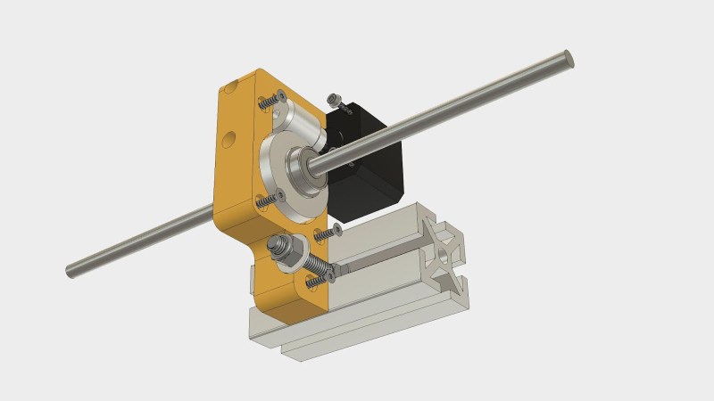
He walks us through the project, starting from initial motivation, moving on to parts selection, and describes how he designed his gearbox parts to work around weaknesses inherent to 3D printing. After the gearbox was installed, the resulting print came out flawed. 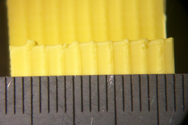 Each of the regularly spaced print bulge can be directly correlated to a single turn of the worm gear making it the prime suspect. Then, to verify this observation more rigorously, Z-axis movement was measured with an indicator and plotted against desired movement. If the problem was caused by a piece of debris or surface damage, that would create a sharp bump in the plot. The sinusoidal plot tells us the problem is more fundamental than that.
This particular worm gear provided enough lifting power to move the print bed by multiplying motor torque, but it also multiplied flaws rendering it unsuitable for precisely positioning a 3D printer’s Z-axis. [Mark] plans to revisit the idea when he could find a source for better worm gears, and when he does we’ll certainly have the chance to read what happens.


This is actually pretty common and can be partially rectified by also using a linear slide of some sort.
The Z axis uses linear guides.
Okay, so the worm gear is not good, but I don’t understand, in what way, is it non-linear?
One of the key specs in a printer’s Z axis is accuracy. The layers we print in are small and they need to be uniform in thickness or defects in the print result. In this case, the worm gears spins 1 rev every 2 mm in the Z axis. The flaws in the print that are spaced at 2mm intervals are because the layer thickness is varying in a repeating pattern. This plot https://3.bp.blogspot.com/-2ib_XqzaKBw/WsvedT1diyI/AAAAAAAAVVY/oxvVzM-Opwcpji153D0QeEN8EGSBt4KQACLcBGAs/s1600/error.png
shows the error in position of the bed moved in 0.1 mm steps of a 4 mm range. There are two cycles in the error plot which corresponds to the 1 rev of the worm gear per 2mm of motion in the Z axis.
Notice that the error repeats, so precision is high. Accuracy is poor, but could be improved with some software that would tweak the gcode depending on the absolute position of the Z axis. It would require measuring the error then programming the inverse of the error curve. You could even do it using a post processing script on the gcode file in which you subtract the error from every movement in the Z axis.
When you consider that autoleveling was developed to allow poorly constructed printers to work anyway, this might be the next place to apply some software, but only if belt lifting the Z axis becomes a thing.
Or maybe such software would allow cheap belt lifted Z axes to become a thing…
That gear surface looks pretty rough, maybe it’s lighting but they are sliding surfaces after all. I also second for double pulley reduction on that shaft ends.
I think you’re mistaking the photograph of the printed part with a photograph of the gear. No, the gear is an inside thread to ride on the outside threaded rod. That photograph of yellow stuff is the evidence of the flaw in the printer, and the fact that it’s always regularly occurring, not a single-event upset.
No no, I’m talking about metal gear. Open his photo in full screen, does it look ok for you?
https://1.bp.blogspot.com/-B_BxtdsXdnY/WspecAIOpEI/AAAAAAAAVU8/yFv6yWspLNs-RbQAvWLBIq2-ma8b-ejgwCLcBGAs/s1600/03290002.jpg
The gears are molded and sintered, so the surface is a little rough compared to machined parts. But that’s why they are cheap…
The article mentions the bore of the worm gear possibly being off-center.
It looks like the issue is not only the position error on the z axis but it seems to introduce some wobble on the XY plane as well. Attaching the gear wheel to the rod via a secondary belt might help.
Yeah, his design leaves a lot to be desired. He has some sort of plastic slider that rides in the grooves of the extruded aluminum, that is just not going to be rigid enough for something like this. Install some thk rails and I bet it will make a world of difference.
There’s nothing sliding in the t-slot. The Z axis (https://drmrehorst.blogspot.com/2017/07/ultra-megamax-dominator-z-axis-design_65.html) uses two THK linear guides.
The 2 mm repeating error int he Z axis is caused by variation in the layer thickness due to imperfections in the gears, specifically the worm gear which spins once for every 2 mm of Z axis movement.
LinuxCNC can correct linearity with an arbitrary piecewise-linear curve. Doing it via gcode, among other things would me up trajectory planning.
The Z axis design was posted in three parts, with the final here: https://drmrehorst.blogspot.com/2017/07/ultra-megamax-dominator-z-axis-design_65.html
The print problem is caused by the extruder spitting out exactly enough plastic for a specific layer thickness, say 0.1 mm, but the layer thickness is varying because of the physical position of the Z axis is not where it is supposed to be due to defects in the gears. Fixing the problem by tweaking the Z coordinates in the gcode would not mess up the planning, it would fix the problem by moving the Z axis to the place where it is supposed to be. If the error in a layer is known to be +20 um, so that layer will be 120 um thick instead of the 100 um that the extruder is expecting, you correct the error by subtracting 20 um from the Z coordinate for that layer.
I don’t think the worm gear is the culprit. the belt is also 2mm pitch and i am very interested it the idler and tensioning wheels. are these toothed or smooth?
Before I tried the new gear mechanism with the 2 mm belt, it used a 3 mm pitch belt and there was no such periodic error. I have since put the 3 mm pitch belt back on the machine along with the Rino worm drive that was originally there and there is no 3 mm spaced error. The top pulleys in the Z axis are smooth bearings.
Correcting this in telescopes is Periodic Error Correction and basically, what it requires is a sensor and a profile like the error one shown. It allows it to move to account for flaws so that the error due to the worm is corrected.
Errors in the larger gear don’t lead to the periodic nature, until you start getting to full rotations of the gear, something that Telescopes don’t have to deal with on any usual mount. If it’s an integer relation, to the worm, then that could be incorporated to the correction.
One example I know of that’s arduino based is the code in OnStep (google onstep telescope)
What sort of sensor is used to measure the error? That sounds like a closed loop system in which the position is controlled by feedback using the sensor to detect error in real time. Unlike the X and Y axes, the Z axis motion would be relatively easy to convert to closed loop operation. Hmmm.
If the tooth profile is wrong on the large gear it could result in periodic error
The disc gear turns once for every every 80 mm of Z axis movement so errors in the disc gear will tend to repeat every 80 mm. It’s possible there is some sort of periodic error in the disc gear that shows up every 2 mm, but that would be a heck of a coincidence. In the 165 mm tall test print, the only visible error is the 2 mm spaced Z banding. It may be that there is some error in the disc gear also that is being masked by the severity of the 2 mm banding, and if that pattern weren’t there, a repeating 80 mm pattern might be visible.
Let’s make experiment.Replace big gear with pulley and one way (clutch) bearing and run print.
If
error is gone > culprit was identified
else
is’t something else
;)
How would you replace the disc gear with a pulley?
I wonder if a windshield wiper worm gear kit will work and what the specs are on the range of different types available. I was looking at for using with a truck cap lift inspired by The Post Apocalyptic Inventor “Build Powerful Linear Actuators from Windshield Wiper Motors and Car Jacks” youtube video.
Car seat adjusters and wiper motors are often worm gear driven, but I see two problems with them. The motors they use are DC motors, not steppers, and converting them may be a problem. You can always take them apart and make a gear box to fit them.
Also, the gears in those parts are not machined for high accuracy, so they will probably be as problematic as the gears I tested.
But the only way to know for sure is to test it…
Makes sense. I wasn’t sure, so I mentioned. Thanks for the heads up on car seat adjusters also. Didn’t know to look there as they might take a heavier load.