Save The Tally Ho: Rebuilding A Historic Yacht

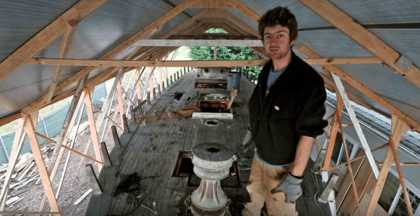
[Leo Sampson Goolden] is a boatbuilder and Sailor. He’s a prime example of a dwindling group of shipwrights who build sailing vessels the traditional way. In 2017, he was given the opportunity to buy Tally Ho, a Yacht built back in 1910. Once a proud ship, Tally Ho now sat as a shell under a shrink-wrap tarp. Her deck was rotted, her keel cracked. Any sane person would have moved on. Thankfully [Leo] is not quite sane, and began a quest to bring this history ship back to its former glory.

Tally Ho isn’t just an old boat. She is a 48-foot long gaff cutter yacht designed by the famous Albert Strange and built in Sussex, England. Tally Ho won the 1927 Fastnet Race (corrected time) when rough seas caused all but two boats to bow out.

To say [Leo] has his work cut out for him would be an understatement. Tally Ho lived a hard life, from racing to fishing. A complete restoration was needed. In fact, it would have been cheaper and easier to build a replica rather than restore the original. [Leo] wanted to save Tally Ho though, so he bought the boat for one dollar, and began to put all his time, effort, and funds into restoring her. This work includes carefully documenting each piece as it is removed.

Some of the tools and materials are traditional – such as chisels and red lead putty. But [Leo] is using power tools as well, including a custom-built chainsaw mount for shaping the keel. His videos are entertaining and illustrate many techniques of boat building. Wherever possible, [Leo] adds captions to explain the meanings of boat building terms, as well as explains the different terms used in England and the USA. In the latest video, you can watch along as [Leo] creates a Dutchman to fill in a knot in the keel. Can check that out in the video after the break.

Continue reading “Save The Tally Ho: Rebuilding A Historic Yacht”

Impossibly Huge Depth Of Focus In Microscope Photographs

Sometimes, less is more. Sometimes, more is more. There is a type of person who believes that if enough photos of the same subject are taken, one of them will shine above the rest as a gleaming example of what is possible with a phone camera and a steady hand. Other people know how to frame a picture before hitting the shutter button. In some cases, the best method may be snapping a handful of photos to get one good one, not by chance, but by design.

[The Thought Emporium]’s video, also below the break, is about getting crisp pictures from a DSLR camera and a microscope using focus stacking, sometimes called image stacking. The premise is to take a series of photos that each have a different part of the subject in focus. In a microscope, this range will be microscopic but in a park, that could be several meters. When the images are combined, he uses Adobe products, the areas in focus are saved while the out-of-focus areas are discarded and the result is a single photo with an impossible depth of focus. We can’t help but remember those light-field cameras which didn’t rely on moving lenses to focus but took many photos, each at a different focal range.

[The Thought Emporium] has shown us his photography passion before, as well as his affinity for taking the cells out of plants and unusual cuts from the butcher and even taking a noble stab at beating lactose intolerance.

Continue reading “Impossibly Huge Depth Of Focus In Microscope Photographs”

Fake Omron Relays Are Worth What You Pay For Them

We love taking a look at fake components and [BigClive] has put together something really special in this category. When he saw he could buy suspiciously cheap Omron relays on eBay, he knew something must be fishy so he put in an order.

Some of the fakes he received are even marked Omrch instead of Omron, and your ear can detect the counterfeits by the varying sounds they make during operation. But of course [Clive’s] investigation goes much deeper than that. He started driving the relays to their rated voltages and taking temperatures with a FLIR camera.

The results were not surprising. At lower voltages the relays seemed to do okay, but closer to the maximums it’s obvious the components in the fakes are not rated for enough power to work. You can even see some charring of a resistor and its plastic holder from having too much power for the component’s rating. [Clive] actually replaced the errant resistor with a higher value resistor that reduces the current consumption and power dissipated.

He was also suspicious of the metal content of the contacts. You may think that doesn’t matter, but actually, the composition of relay contacts is critical to making reliable relay circuits. Depending on how much current flows and if the switching is dry (that is, made without current flowing) or not dictates use of different material.

The conclusion was that these relays might work for light duty projects, but for commercial projects or operating near the edge of the ratings, you want to give these a pass. If you do need a lot of low-power relays on the cheap — to compute a square root, or to build the whole computer — [Clive’s] process of testing and characterizing these fakes may come in handy for you.

Continue reading “Fake Omron Relays Are Worth What You Pay For Them”

Flashing An LED The Widlar Way

Regular Hackaday readers will be familiar with the work of Boldport’s [Saar Drimer] in creating beauty in printed circuit board design. A recent work of his is the Widlar, a tribute to the legendary integrated circuit designer [Bob Widlar] in the form of a development board for his μA723 voltage regulator chip.

The μA723 is a kit of parts from which almost any regulator configuration can be made, but for [tardate]  it represented a challenge. The μA723 is so versatile that what you can create is only limited by the imagination of the builder. Having done the ordinary before, [tardate] looked toward something unconventional.

The result is modest, a simple LED flasher using the error amplifier as a not-very-good op-amp, building an oscillator at a frequency of about 2 Hz. This is pretty neat and if you are used to the NE555 as the universal integrated circuit, perhaps it’s time to set it aside for the obviously far-more-useful μA723.

Here at Hackaday we harbour at least one fan of the μA723, not to mention also of artful PCBs. If the Widlar looks familiar, we featured the switch mode regulator from the μA723 data sheet on it a few months ago.

Disclosure: [Jenny List] wrote the documentation for Boldport’s Widlar kit.

Pick And Place Machine Is Mirror Image Of 3D Printer

For his Hackaday prize entry, [Daren Schwenke] is creating an open-source pick-and-place head for a 3D printer which, is itself, mostly 3D printable. Some serious elbow grease has gone into the design of this, and it shows.

The really neat part of this project comes in the imaging of the part being placed. The aim is to image the part whilst it’s being moved, using a series of mirrors which swing out beneath the head. A Raspberry Pi camera is used to grab the photos, an LED halo provides consistent lighting, and whilst it looks like OpenPnP may have to be modified slightly to make this work, it will certainly be impressive to see.

Two 9g hobby servos are used: one to swing out the mirrors (taking 0.19 seconds) and one to rotate the part to the correct orientation (geared 2:1 to allow 360 degrees part rotation). Altogether the head weighs 59 grams – lighter than an E3D v6.

In order to bring this project to its current state, [Daren] has had to perform some auxiliary hacks.  The first was an aquarium to vacuum pump conversion – by switching around the valves and performing some other minor mods, [Daren] was able to produce a vacuum of 231mbar. The second was hacking a two-way solenoid valve from a coffee machine into a three-way unit. As [Daren] says, three-way valves are not expensive, but “a part in hand is worth two on Alibaba.”

Biasing That Transistor: The Common Base Amplifier

We’ve previously remarked upon a generation lucky enough to be well-versed in microcontrollers and computersised electronics through being brought up on the Arduino or the Raspberry Pi but unlucky enough to have missed out on basic electronics such as how to bias a transistor, and to address that gap we’ve taken a look at the basics of transistor biasing.

All the circuits we worked with in the previous article had the transistor’s emitter taken to ground, took their input from the base, and their output from the collector. This configuration, called a Common Emitter amplifier is probably the most common, but it is far from the only way to use a transistor. Once you have set up the bias voltage as we described to the point at which the transistor is in its linear region, there are several other ways in which the device can be used as an amplifier. The subject of this article is one of these configurations, so described because it takes the transistor’s base to the ground instead of the emitter, as a Common Base amplifier. Continue reading “Biasing That Transistor: The Common Base Amplifier”

Fail Of The Week: 3D Printed Worm Gear Drive Project Unveils Invisible Flaw

All of us would love to bring our projects to life while spending less money doing so. Sometimes our bargain hunting pays off, sometimes not. Many of us would just shrug at a failure and move on, but that is not [Mark Rehorst]’s style. He tried to build a Z-axis drive for his 3D printer around an inexpensive worm gear from AliExpress. This project was doomed by a gear flaw invisible to the human eye, but he documented the experience so we could all follow along.

We’ve featured [Mark]’s projects for his ever-evolving printer before, because we love reading his well-documented upgrade adventures. He’s not shy about exploring ideas that run against 3D printer conventions, from using belts to drive the Z-axis to moving print cooling fan off the print head (with followup). And lucky for us, he’s not shy about document his failures alongside the successes.

He walks us through the project, starting from initial motivation, moving on to parts selection, and describes how he designed his gearbox parts to work around weaknesses inherent to 3D printing. After the gearbox was installed, the resulting print came out flawed. Each of the regularly spaced print bulge can be directly correlated to a single turn of the worm gear making it the prime suspect. Then, to verify this observation more rigorously, Z-axis movement was measured with an indicator and plotted against desired movement. If the problem was caused by a piece of debris or surface damage, that would create a sharp bump in the plot. The sinusoidal plot tells us the problem is more fundamental than that.

This particular worm gear provided enough lifting power to move the print bed by multiplying motor torque, but it also multiplied flaws rendering it unsuitable for precisely positioning a 3D printer’s Z-axis. [Mark] plans to revisit the idea when he could find a source for better worm gears, and when he does we’ll certainly have the chance to read what happens.