I don’t have a signal generator, or more specifically I don’t have a low frequency signal generator or a function generator. Recently this fact collided with my innocent pleasure in buying cheap stuff of sometimes questionable quality. A quick search of your favourite e-commerce site and vendor of voice-controlled internet appliances turned up an FG-100 low frequency 1Hz to 500kHz DDS function generator for only £15 ($21), what was not to like? I was sold, so placed my order and eagerly awaited the instrument’s arrival.
The missing function generator is a gap in the array of electronic test instruments on my bench, and it’s one that maybe isn’t as common a device as it once might have been. My RF needs are served by a venerable Advance signal generator from the 1960s, a lucky find years ago in the back room of Stewart of Reading, but at the bottom end of the spectrum my capabilities are meagre. So why do I need another bench tool?
It’s worth explaining what these devices are, and what their capabilities should be. In simple terms they create a variety of waveforms at a frequency and amplitude defined by their user. In general something described as a signal generator will only produce one waveform such as a sine or a square wave, while a function generator will produce a variety such as sine, square, and sawtooth waves. More accomplished function generators will also allow the production of arbitrary waveforms defined by the user. It is important that these instruments have some level of calibration both in terms of their frequency and the amplitude of their output. It is normal for the output to range from a small fraction of a volt to several volts. How would the FG-100 meet these requirements? Onward to my review of this curiously inexpensive offering.
Noisy as Sin
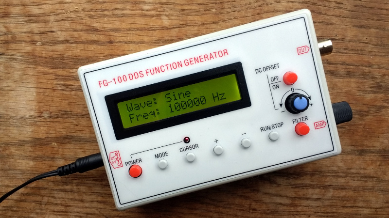
The package duly arrived, and inside was the unit itself with no power supply or instructions. It is well-presented in an ABS enclosure a little bigger than a pack of cards with a custom front panel for the buttons, LCD, a BNC output, plus a knob for the amplitude on the right hand side. On the left hand side is a power jack to supply the required 5 volts. Handily the jack is the same size and polarity as the one used on older 5 volt Nokia phones, so a rummage through the wall wart box yielded a suitable adapter. I’d have expected the ubiquitous micro-USB in 2018, or at least a USB-to-power-jack cable, but sadly neither were present.
Upon power-up, the display lit up with “Wave: Sine” and “Freq: 100000”, and a flashing cursor in the frequency display. There are two modes to the interface, this one in which the waveform can be set, and another in which they are locked while the generator is running. There is a “Run/stop” button to toggle between the two and enable the output, a “Mode” button to select between sine, square, triangle, sawtooth, and reverse sawtooth waveforms, and a mildly inconvenient three-button interface to select frequency. There is also a switchable filter and a switchable DC offset facility. Unfortunately it has no capacity to remember the last settings used, so it will always start with 100kHz.
Evaluating a signal generator is an exercise largely performed with an oscilloscope, in that a modern ‘scope also contains the functions of a frequency counter and through its FFT capability, a rudimentary spectrum analyser. The FG-100 was hooked up to the trusty Rigol, and it’s worth saying that a variety of different termination resistors were used in these tests and were found to make little difference to their outcomes.
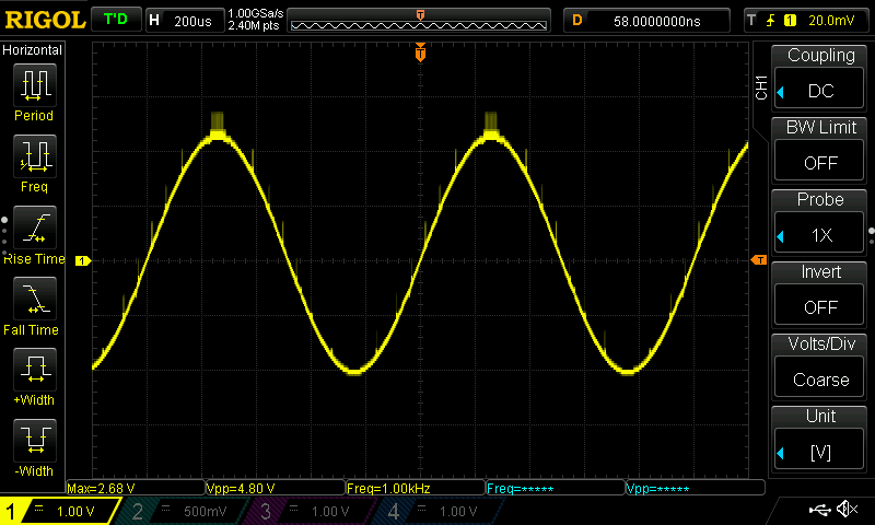
This is a low-frequency generator, so on first activation it was set to 1kHz. There were some visible transients on the waveforms, whichever type was selected. The amplitude was variable from 0 to 24 volts peak-to-peak, and if the DC offset feature was enabled the waveform could be shifted from about -10V to +10V. There is no calibration of any sort upon either offset or amplitude, but all frequencies measured were what the generator claimed it was producing.
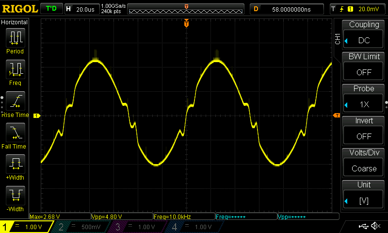
As the frequency was increased there appeared visible distortion on the sine waveform, starting above about 5kHz and becoming really pronounced from 10kHz upwards. Looking at the waveform it is similar in appearance to crossover distortion on a poorly designed class B amplifier, though it is seemingly not subject to such treatment. The distortion increases to the point at which all types of supported waveform approximate to a triangle at 50kHz, after which the amplitude tails off.
Measuring the low frequency square wave rise time at a pedestrian 25μS backs up this discovery, it is evident that this is no 500kHz device. Stepping through the frequency range it produces a detectable signal of some sort all the way up to the 999.999kHz maximum on its interface, but it is pretty evident that its usable bandwidth is only below 50kHz.
Well designed, but let down by poor components?

On the back of the enclosure are four screws, these are long M3 threaded bolts that screw directly into the ABS, they are not the expected self-tappers. Removing the lid reveals the FG-100’s secret, there is no dedicated DDS chip at all but an ATMega328 in a socket at its heart. Other components are what looks like a resistor ladder DAC, a switching power supply chip, a couple of TL072 op-amps for signal conditioning, and an HD4480 clone LCD display that is also socketed. The switches did not seem to be of especially poor quality, and each one had a plastic cap for the front panel.
Conclusion
So given my investigation of the FG-100, what’s the verdict? It’s fairly obvious that I bought it mostly in the continuance of my occasional series of reviews of cheap stuff rather than in the expectation of a high quality instrument, and it’s thus fair to say that it will not join my bench as my everyday function generator. It’s no diamond in the rough, though it’s technically using DDS to create waveforms it has no dedicated DDS chip, its waveforms exhibit distortion and transients, its bandwidth is nowhere near that advertised, and it has no amplitude calibration whatsoever.
It’s a pity because its construction shows some attention to physical design detail, but I can’t honestly recommend that anyone add one to their arsenal of test gear. For your £15 you get an Arduino in a box with a display and a load of buttons, along with a bit of questionable signal conditioning circuitry. Assuming that its designer did originally create a half-decent low-frequency function generator I can only conclude that it has been let down by poor quality or counterfeit components in its analogue section, perhaps at some point I’ll try reverse engineering it to find what’s up. A quick look online finds most other suppliers carrying them for a bit more than what I paid, so perhaps I even got suckered with some kind of knock-off.
You’re probably asking why anyone would have expected more for such a small outlay and you’d be absolutely right, but then again if you’ve followed my reviews in this vein you’ll be aware of the joy to be found in poking into poor quality hardware. It’ll join the comical multimeter and the disintegrating desoldering pump. But lest you think all £15 purchases are junk you should take a look at the much better temperature controlled soldering iron and pocket oscilloscope.


Thanks Jenny. I like it when you buy junk so we don’t have to, ha ha. I also like how every once in a while, you discover something decent for not much money.
Being honest, I can and will run out and buy a “proper” instrument. But yes, there’s a joy in the slightly awful. :)
I have replaced the TL072’s with LF412’s. Now the signals are quite good up to 200 KHz than the Amplitude goes down to 5Vss at 500 KHz, but stll as SINE.
“I don’t have a signal generator, or more specifically I don’t have a low frequency signal generator or a function generator. ”
Tell ya what Jenny, I have a funky I could give you. I think I had 3 at one point, 1 cost me $1, and one I picked out of a skip/dumpster after a college auction, and I’m not sure what I paid for the other.
Contact me through Mike (I’d like to buy a vowel) Szczys with a snail mail address and I’ll mail one to you. (I’m sure you are capable of converting it to 230 volts or whatever)
It’s a wonderful offer, but I don’t think you’d be happy at the eye-watering cost of mailing it to the UK. But thanks. :)
As it happens I’ll probably be wandering out and getting one of the “real” DDS ones.
I was just wondering if ebay had any cheap function generators like this. Guess I’ll have to keep looking
It’s nice to have around, especially for the money. While there are some distinct limitations, it’s pretty solid on the lower end and it being battery powered means that you can use it floating. It’s definitely useful, even with an AWG next to it.
I have one similar to this, but paid more (about £65 a few years ago) for an arbitrary waveform generator, useful for ultrasonic stuff
, as you can plot your own waveform and upload it, it will save 10 waveforms.
I bought an xr2206 based function generator kit from amazon for $12 shipped and you can get them even cheaper on ebay if you’re willing to wait for it to go through china post. It’s able to produce a pretty reasonable sine wave up through several 100khz and even at 1Mhz there’s only a little distortion.
What?! There’s no microcontroller in your function generator!
This generator should not exist in this day and age. For a lousy $2 you can add a real DDC chip like the AD9833, which will outperform it by a long shot.
here is a nicely built one http://vwlowen.co.uk/arduino/AD9850-waveform-generator/AD9850-waveform-generator.htm
Nice
The AD9850 [or AD9851] modules are a great start. Combined with an Arduino and a logarithmic power meter, they make up the “Poor Hams Scalar Network Analyser”.
Typically work from almost DC, up to about 30 – 50 MHz depending on the chip.
This box is very likely based on Jesper’s mini DDS.
If you want to toy around with Jesper’s mini DDS, then I suggest to buy one of the EUR7,5 kits from:
https://www.aliexpress.com/wholesale?SearchText=DDS+Signal+Generator+Function+Generator+Module
Disadvantage ot that kit is that it needs 2 voltages +12V -12V and +5V (No on board voltage regulators).
“Decent” signal generators start at around EUR60. Take for example the JDS6600.
Plenty of reviews on youtube and on the EEVblog forum.
Oh, and please stop every board with an atmega an “arduino”.
I hate those things.
“Oh, and please stop CALLING every board with an atmega an “arduino”.”
FTFY
Very true on Arduino. But it’s a generalisation, I’m sure readers can tell it isn’t.
But once you realise it’s utter dung, you can reprogram the atmega (either within or without the current circuit), possibly through use of the arduino IDE
What if they used the similarly inexpensive STM32F103 ?
F103 does not have a built in dac, but if you use a similar STM32 with built in DAC (and use DMA) then you can build a nice low frequency arbitrary waveform generator with very low cost.
That ATmega used in the reviewed FG-100 signal generaotr is not using it’s native DAC either, if it even has one.
There is an external R-2R resistor DAC made from discrete SMD resistors.
It works well if properly designed and driven.
True, R-2R works pretty well. JDS660 has R-2R (And I believe 12 bit DAC).
But when you go ARM there is no reason to not pick one without DAC, which saves you layout and soldering of the R-2R network. Why add 20 external resistors, if an ARM with built in DAC is about the same price as one without?
But more important is the DMA to speed up data transfer and to give the uC time to handle buttons and display.
I’m not sure though if the DDS algorithm can be put completely in the DMA peripheral.
Using 2 DMA channels and clever reprogramming might be neccasarry.
That ‘crossover distortion’ is a pretty clear indication that the tolerance of the resistor ladder DAC they’re using is poor. It occurs when the resistance of b01111111 exceeds the resistance of b10000000 (eg a resistor with nominal value 2n is actually lower in resistance than the sum of all the smaller resistors).
I first thought of a silly mistake in the DDS LUT, but resistor tolerance (or misplaced resistor, bad solder joint) seems indeed more logical.
R-2R ladder dacs are also used in the JDS6600 which has pretty decent specifications.
Good point. I suspect I’ll be doing a bit of diagnostics for my own edification. That’s a good place to start.
After seeing some youtube’s where it does ouput some decent sine waves (within it’s limitation) Jenny’s unit surely seems to be faulty.
Probably easy to compare, but it would be nice to contact the seller for a replacement and/or to test the service of the shop where it was bought.
Edit: compare -> repair
First thing when I saw the fisrt photo of glitches, was could they be using an R/2R? And then, Nah. Nobody would do that now. OTOH, the resistors are less than 1/10 cent each, so yeah. Having used 1% resistors (you need better) for video way back (8 bits each RGB and 7MHz driven by 74HC buffers) I know a lot about getting it right.
A cool follow-up would be to use a single input pulse, and a fast ADC + FFT of the output to fully plot bandwidth and phase for a circuit. Today, your PC does FFT (and correlation and deconvolution) so quickly that you get a very high resolution result before you can say Jack Laplace!
https://www.youtube.com/watch?v=KlFnaRGsrrk
https://hackaday.io/project/7985-alternate-firmware-for-fg-100-dds-function-gen
https://github.com/timsavage/fg100alt-firmware/
Sorry for posting the links without further comment.
Though they are self explanatory, I should have known they do not get through the spam filter without moderation.
After seeing some more youtube’s I am a bit dissapointed that I haven’t seen closer screen captures of the PCB yet.
Most of it is pretty obvious though:
– AVR, R-2R, LCD is already a big part of the circuit.
– Blue pot on the left is probably for LCD contrast.
– U2 seems to be an AM1117
– The inductor next to it is probably from a small SMPS circuit for a negative voltage.
– Few opamps (Both TL072?) for buffering, amplification andthe “filter”
– The crystal has: “30.000” printed on it. I have also heard some reference of a 40MHz crystal.
– What is the use of the potmeter in the lower right corner? (RV4).
Waiting for camera’s to focus onto wobbly handheld pcb’s is not really my idea of best practice.
Saying he uses his phone is no excuse for that. They are not like the potato’s they were and some seconds of the video are clearly sharp enough for a decent view of the PCB. You can even read the resistor codes and “TL072C” on the chip.
Changing some of the push buttons with a rotary encoder would be an easy and nice hack.
Disadvantage of this (very simple) circuit is the tight ASM loop for the DDS algorithm.
Every button push or character written to the lcd will generate glitches in the output signal.
Probably not such a big deal if you are aware of it though.
Combination of using some ARM Cortex uC with a higher F_CPU, hardware DAC and DMA to de-couple the DDS algorithm from the rest of the software would be a nice project also.
I would instantly buy such a kit if it came in the form of an open source project, but as it is I am not interested in it enough to develp / port the software myself.
RV4 is a trimmer pot to centre the waveform.
I’ve since moved on to building my own from scratch using a pair of micros to handle software and DDS. Still get questions pop up regarding the firmware. The crystal is 30Mhz although I have had reports of the output frequency being 1/3 on both the stock and my firmware leading so seems that sometimes a 10Mhz crystal is used.
Thank you for the review, Jenny!
I got one of these about 4-5years ago (around the time I did the reverse engineering and re-writing of the firmware) and I PCB in your one looks a lot cheaper, many of the parts also look cheap. Mine came with Rubycon caps and the PCB includes versioning and part numbers. Mine also outputs a very clean 1Khz signwave.
Since I posted the alternate firmware I have had a lot of questions (more of late) regarding noisy output, the common solution has been to replace the op-amps.
Intersil ICL8038: totally self-contained waveform generator. And not a microcontoller anywhere.
… and nonexistent.
Only if you don’ t know how to do a search…
You can take the improved MAX038 if you want.
The MAX038 went out of production ages ago and never replaced by Maxim, all those being sold online are either relabeled fakes or overpriced NOS stocks. As far as I know, nobody ever cloned it like it has been done with both the XR2206 and ICL8038 (similar function and name but totally different pinout and ratings). Also all those 2206 and 8038 based kits contain cloned chips and their perfomance is often sub par compared to the real things, though they still perform a lot better than cheap badly designed DDS generators like pretty much all those not using specialized chips.
Question–
Why doesn’t someone use the Raspberry Pi 3B+ to provide the software power for a device such as the AD9833/AD9850/AD9851?
Seems to me that the RPi in conjunction with a PiHat using one of these devices–or a similar device–would be a dynamite application.
Forget the PiHat; how about a less-than-custom-design which simply interfaces an RPi to a well-designed ‘custom breadboard’ capable of supporting these devices’ (approximately) 20 MHz capability.
It seems as though one could have a very good function generator for not much cash outlay.
Why was my comment/question about building a function generator using a Raspberry Pi 3B+ and an AD9833/9850/9851 deleted?
Simple question. Seems like a great hack to me. Did this offend someone? Maybe someone who doesn’t know how to do it?
Any answer(s)?
I think your other question was stuck in the pending moderation queue. Looks like it’s live now.
In my opinion you would be off buying a cheap function generator off EBay and making modifications on it. The Exar 2206 makes a good quality function generator. Kits usually sells for about 8 to 10 dollars.
nice review of this generator…. The biggest fault I have with it is the inability to use an encoder or pot to sweep the signal frequency. I really want to be able to tune US transducers and think this will be a pita if I try and do it with the current interface. Before I send it back to Amazon, has anyone looked at adding an encoder to set the frequency, or is this just not possible with the firmware?
Thanks folks,
Doug
@Jenny List : I have the same signal generator and a Rigol DS1102Z-E scope.
I cannot find *any* of these weird artefacts you are showing, which you say start at around 5 kHz?
Either there must be something wrong with your test setup, or you have received a faulty unit.
To keep a clean signal , do not max out the amplitude knob (which gives up to 24Vpp) and disable the DC offset button.
The sine wave looks very clean up to the full 500 kHz on my unit. (Vpp slowly decreases when increasing the frequency if you leave the amp knob untouched)
I’m very happy with this signal generator, it might be worthwhile to try to locate a faulty component on the pcb on your device?
What I’d really like to do is find the FG 100 enclosures for my own DDS.
Any ideas?