
Temperature is one of the most frequently measured physical quantities, and features prominently in many of our projects, from weather stations to 3D printers. Most commonly we’ll see thermistors, thermocouples, infrared sensors, or a dedicated IC used to measure temperature. It’s even possible to use only an ordinary diode, leading to some interesting techniques.
Often we only need to know the temperature within a degree Celsius or two, and any of these tools are fine. Until fairly recently, when we needed to know the temperature precisely, reliably, and over a wide range we used mercury thermometers. The devices themselves were marvels of instrumentation, but mercury is a hazardous substance, and since 2011 NIST will no longer calibrate mercury thermometers.
Luckily, resistance temperature detectors (RTDs) are an excellent alternative. These usually consist of very thin wires of pure platinum, and are identified by their resistance at 0 °C. For example, a Pt100 RTD has a resistance of 100 Ω at 0 °C.
An accuracy of +/- 0.15 °C at 0 °C is typical, but accuracies down to +/- 0.03 °C are available. The functional temperature range is typically quite high, with -70 °C to 200 °C being common, with some specialized probes working well over 900 °C.
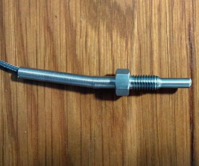
It’s not uncommon for the lead wires on these probes to be a meter or more in length, and this can be a significant source of error. To account for this, you will see that RTD probes are sold in two, three, and four wire configurations. Two-wire configurations do not account for lead wire resistance, three-wire probes account for lead resistance but assume all lead wires have the same resistance, and four-wire configurations are most effective at eliminating this error.
In this article we’ll be using a 3-wire probe as it’s a good balance between cost, space, and accuracy. I found this detailed treatment of the differences between probe types useful in making this decision.
Circuits for Reading a Resistance Temperature Detector
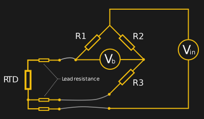
Unfortunately, RTDs come with a few difficulties. Mainly, they are a resistive sensor and subject to self-heating with anything but the smallest of currents, requiring a constant-current supply. You might build this out of operational amplifiers and a wheatstone bridge.
Not all of us enjoy analog circuit design, and there is a decent IC that will handle it for you: the MAX31865 RTD to digital converter. It works by comparing the RTD probe resistance to a reference resistor, and is fairly easy to design a board around (the chip is available in both SSOP and TQFN form factors). This chip is readily available in pre-assembled Arduino-compatible modules, and is supported by an Arduino library. However, that’s not for everyone, and today we will cover how to interact with this useful chip over SPI.
Regardless of your platform, most MAX31865 modules require some initial setup. Some areas of the board will have to be bridged or have traces cut to set what type of probe you are using.
A Test Run with ESP8266 and Lua
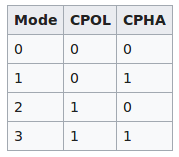
In this example, I’ll be using Lua on an ESP8266 microcontroller running NodeMCU, but similar steps should work on a platform of your choice. Our first step will be to configure SPI. The MAX31865 datasheet (PDF) states that only SPI modes 1 and 3 with 8 data bits, and a maximum clock of 5 MHz are supported. A quick search on Wikipedia returned a table with the SPI settings for each mode.
I chose SPI mode 1 and a hefty clock divider of 256. I also set up an output pin to use as the Chip Select pin. This pin needs to be driven low to initiate reads and writes, then driven high once the operation is completed. The resulting code is:
pin = 1
spi.setup(1, spi.MASTER, spi.CPOL_LOW, spi.CPHA_HIGH, 8, 256);
gpio.mode(pin, gpio.OUTPUT)
Next we define sending and receiving functions based on the required behavior of the Chip Select pin. The returned integer after a read will always be between 0 and 255. The ESP8266 will interpret this as an ASCII character, so we use string.byte to convert it to a decimal value:
function spi_write(target, data)
    gpio.write(pin, gpio.LOW)
    tmr.delay(20)
    spi.send(1, target)
    tmr.delay(20)
    spi.send(1, data)
    gpio.write(pin, gpio.HIGH)
    tmr.delay(20)
end

function spi_read (target)
    gpio.write(pin, gpio.LOW)
    tmr.delay(20)
    spi.send(1, target)
    tmr.delay(20)
    x = spi.recv(1,1)
    print (string.byte (x, 1))
    tmr.delay(20)
    gpio.write(pin, gpio.HIGH)
    tmr.delay(20)
end
Configuring MAX31865 Behavior
Using the SPI read and write functions, we can now use the MAX31865 chip. There are only 8 registers on the chip, each containing 8 bits of data. To read from a register we precede it with a ‘0’, and to write to it, an ‘8’. For example, to read from register 1 we would use spi_read(0x01), and to write the number 0xFF to it we would use spi_write(0x81,0xFF).
The main configuration register is register 0 and it works according to the following table:
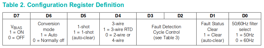
Since I want to automatically read every second, I need to turn on both Vbias and set conversion mode to Auto, so that’s ‘11’. I don’t want to use 1-shot, so that gets written ‘0’. I’m using a 3-wire probe, so that’s a ‘1’. I’ll clear fault detection for now, so that’s ‘00’. I want to start with fault status clear, so that’s a ‘1’, and the electrical frequency in my area is 50Hz so that’s a ‘1’ too. Concatenating that all together, we get ‘1101 0011’ or hexidecimal 0xD3.
spi_write(0x80, 0xD3)
The chip supports alert thresholds when the temperature goes above or below a value. I won’t be using these, so I’ll set them to extreme values.
spi_write(0x83, 0x7f)
spi_write(0x84, 0xff)
spi_write(0x85, 0x00)
spi_write(0x86, 0x00)
Reading Temperature Data
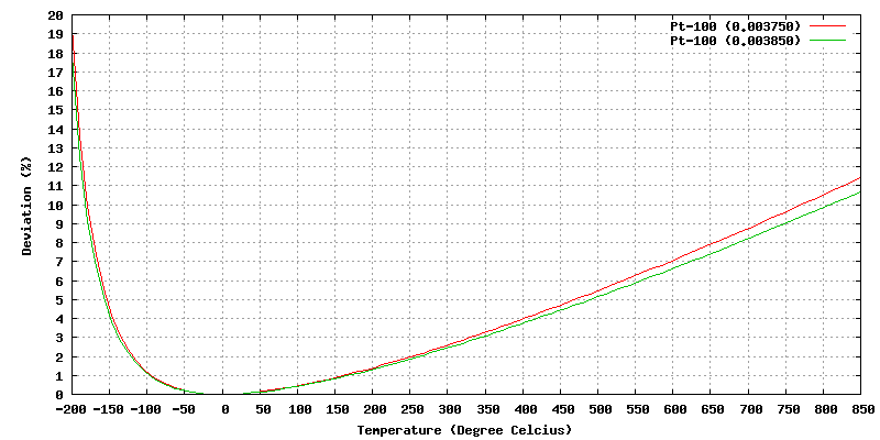
Now that it’s set up, we can finally read data. The data are 15-bit ratios between the reference resistor (in my case 427 Ω) and the RTD probe. As the temperature of the probe increases, its resistance increases in a nearly linear fashion.
According to the datasheet, the temperature can be approximated from this with the formula:

However, there’s a good reason not to do this: the error is up to 1.75 °C in the range of +/- 100 °C. Also it assumes a 400 Ω reference resistor, so you’ll likely need to correct for that. This level of accuracy is not significantly better than cheaper, easier-to-use devices, but is useful to determine if your probe is more or less reading correctly.
To improve accuracy, we have to consider the slight nonlinearity of the relationship between probe resistance and temperature. There are a few ways to do this, but the most commonly used is the Callendar-Van Dusen equation. This is typically a second-order polynomial of the form that predicts the resistance at a given temperature as:
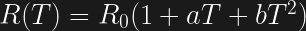
This is accurate up to about 660 °C (more complex functions can handle higher temperatures). The probe specification states that the values for a and b are 3.90830 x 10⁻³ and -5.77500 x 10⁻⁷ respectively. With those constants, we can write an implementation as follows:
#Read high ADC register (8 bits)

gpio.write(pin, gpio.LOW)
tmr.delay(20)
spi.send(1, 0x01)
tmr.delay(20)
x = spi.recv(1,1)
x = (string.byte (x, 1))
tmr.delay(20)
gpio.write(pin, gpio.HIGH)

tmr.delay(20)

#Read low ADC register (7 bits)
gpio.write(pin, gpio.LOW)
tmr.delay(20)
spi.send(1, 0x02)
tmr.delay(20)
y = spi.recv(1,2)
y = (string.byte (y, 1))
tmr.delay(20)
gpio.write(pin, gpio.HIGH)

#print out approximation of temperature from function in datasheet, accounting for our resistor being 427 Ω, not 400 Ω. Note that the ADC value is 15 bits long, not 16.

z = tonumber(x)*127+tonumber(y)
z = z*(1.0675)
z = (z/32) - 256
print (z)

#implement Callendar-Van Dusen equation to provide more accurate result
a = 0.00390830
b = -0.0000005775
z = tonumber(x)*127+tonumber(y)
z = (z/(2^15))*427
z = (-100*a+((10000*(a)^2) - 400*b*(100-z))^0.5)/(200*b)
print (z)
This worked quite well, with the Callendar-Van Dusen equation providing a result of about 0.15 °C higher than the approximation at 30 °C.
If you’re still holding out and have a mercury thermometer, it might be time to take a deep breath (assuming it is intact), put aside the nostalgia, have it recycled, and move on.


This may be a dumb question for someone that knows the answer.
Why can you not take a 2wire RTD and wire it up with 4 wires.
Then you’re measuring the resistance of the wire pairs to the RTD at each side and subtracting.
As from the article the 3wire and 4wire options are for measuring the resistance of the wire.
I dont follow why you cannot just make a 4wire RTD solution from a 2 wire one.
If thre are extra resistors inside of them, they are fixed values.
The article suggests you buy them in differnet wiring configurations with different numbers of leads.
But that seems redundant.
Even the MAX31865 datasheet suggets you roll your own so to speak.
That’s exactly how 4 wire RTDs are built. Two wires connect to one side of the sensor and 2 wires connect to the other side. Then 1/2 the loop resistance is subtracted from the total resistance. But as long as all wires are the same a 3 wire RTD works just as well. We use 3 wire RTDs for our home bbrewery controllers.
Well I thought so, but the fact that you can buy 2 wire ones or 4 wire ones…
I suppose if you are not adding a long lead to them sure it makes sense.
I went off to find the accurary difference in a PT1000 and a PT100.
It’s quite significant.
http://blog.wika.com/knowhow/pt100-in-2-3-or-4-wire-connection/
I understand why my solar water collector controller uses a PT1000 and doesn’t bother with 4 wire.
I guess unless you want hyper accuracy it’s PT1000 and 2wire.
Or given the extra parts, potentially DS1820 and family, etc. (which I use a lot personally).
They used a 2 wire PT1000 because it’s cheaper than 3 wire PT100 to manage. They did not need a compensation circuit to subtract the sensor wires.
That wikia article is terrifically inaccurate. The listed amounts for measuring error are completely out to lunch, maybe if you buy the cheapest of the cheap pt100’s will they have an error of 4-5C.
We use 3 wire pt100’s for BMS systems for livestock and the ones we buy from Omega have a 0.5C error, and we can get less. It all depends on which metal is used for the wire resistor, good platinum ones have much smaller tolerances.
The classic four wire resistance measurement arrangement uses one pair of wires to pass the current through the resistance and the other pair of wires to measure the voltage across the resistance. You measure the current and voltage at the measuring instrument end of the cable (not the RTD end) and if the voltage reading instrument is has a very high impedance there will be no extra voltage drop contributed by the voltage measuring pair of wires because the high impedance voltmeter causes very low current in the voltage measuring pair of wires.
So all you have to do to have high accuracy measurements of temperature is keep the current low so no self heating and use high accuracy current and voltage measuring devices.
Oops, didn’t see regnips comment below.
They are generally purchased as a sealed unit.
In a three wire of four wire unit, the third and forth wires are connected at the sensing end and carry negligible current, as they are only used for measuring potential across the calibrated portion of the element. They are brought out with the current carrying leads.
The sensing element (platinum wire) can be damaged physically if exposed. If you purchase a 2-wire unit, you would need to disassemble it to add the other two wires, and, in that, you would lose the calibration, as well.
In the cheap RTDs I’ve taken apart (to troubleshoot), the platinum wire element is a small, sealed, thin film component. That component is in turn sealed again in a mechanically robust steel shell that conducts heat to the RTD.
The 2/3/4 wires of the probe are just attached (likely welded and not soldered) to the lead wires of the thin-film component. The wires are short, but long enough to work with.
So if mechanical durability is not a concern, you could create a 4 wire probe out of a 2 or 3 wire one by disassembling the probe and spot welding more wires to the lead wires of the small RTD element.
In practice the mechanical durability of these pre-assembled probes is one of their best features so this won’t usually be a great thing to do. On the other hand, let’s say you wanted to track the temperature of an IC — extracting the tiny RTD element and attaching it directly to the chip might be a good way to do this as you will be reducing the thermal mass of the probe. At this point, you may as well attach a few more wires.
I expect you could encounter other issues doing the above, but I can at least imagine a situation where you have a 2 wire probe and welding on some spare wires would be practical.
You could also just buy the raw Pt100 element if you expect to be doing this a lot. They are significantly less expensive this way.
PT100’s with wire lead terminations are available from Digikey for less than $2.00 each.
https://www.digikey.com/product-detail/en/te-connectivity-measurement-specialties/NB-PTCO-002/223-1773-ND/5272150
Also, adding additional wires to the leads of a 2 wire PT100 sensor works very well because the last mm of wire leading into the sensor matters very little. In our case, we run a 6 foot 3 wire 22 AWG copper wire to our brewery sensors and using a 3 wire connection zeros out about a 1 degree F error.
The 4-wire can be a Kelvin connection. You can pass a known current, from a constant current source for example, through one pair (one in and one out) and use the other pair with a high impedance device like an op-amp. The current in the high impedance pair is nearly zero, therefore the IR drop is basically zero. This gives very accurate measurement and wire length can be ignored.
Hey, until a few weeks ago I was a manufacturing engineer for an RTD manufacturer. All RTDs are just a single nonpolar resistor, and you have one or two lead wires attached to either end of that resistor. Because you’re trying to accurately measure the calibrated and predictable resistor portion of the assembly, the resistance of your wires is really important too. After a few feet of wire, you can basically forget about having a calibrated value for your sensor, if you’re using it as a 2 wire RTD. The added resistance of a few feet of copper wire and the possible variation between wires, along with the temperature coefficient of resistance for that copper wire, will make your measurement pretty worthless. This can be mitigated with thicker lead wires, but that has its own issues (size, cost, etc). You can also help this out by getting a 1kOhm RTD, since the proportion of lead wire resistance will be smaller. Adding a third wire significantly improves the capabilities of the sensor, and the cost isn’t that great to add a third wire, particularly for shorter lead lengths. The only real issues you run into with that is cost for long distances, cable availability, and the space you’re trying to fit your sensor into. 3 wires cancels out the average lead wire resistance, which is really accurate as long as your wires are close in resistance. Really long wires end up being a problem, so while 3 wires is cheaper and roughly as good as a 4 wire measurement for shorter distances, long distances need 4 wires, because variability in lead wire resistance can’t be avoided easily over really long distances, particularly in cables where you can’t mix and match wires to get sets that have close resistance values. And eventually when your wires get long enough, you really should just switch to a transmitter that can read your resistance and send the value back to a controller over a 4-20 mA signal.
Having said all of that, you could just add a second wire to each lead on a 2 lead RTD and take a 4 wire measurement, but you’ll also be measuring the 2 wires up until that splice point, which adds some resistance and that resistance value will also shift with temperature. Hope that helps, maybe somebody else already explained it well enough. If you have more questions I can try to answer them.
For easy access from a uC to temperature measurement with really high accuracy or resolution, remember that a lot of “modern” sensors have built in temperature measuremt, which is often mainly there for temperature compensation of the sensor.
A good example of this is the (very common) BPM280. It has a gazillion bit ADC for air pressure measurement (resoluton of 10cm of air column or so) and it reads the built in temperature sensor with the same ADC. Temperature resolution is 0.01 Celcius.
https://ae-bst.resource.bosch.com/media/_tech/media/datasheets/BST-BMP280-DS001-19.pdf
I’ve used this sensor as well. It was a surprising amount of work to communicate with it over SPI, at least for the air pressure component.
The precision is indeed high but the accuracy is +/- 1 degree Celsius. This is accurate enough for many purposes and for the sensor to compute the air pressure.
When I’m measuring “comfortable” temperatures, my favorite is the Si7021 which is accurate to 0.4 degrees Celsius and 3% relative humidity over a reasonable range. The modules cost me about 5$ locally.
I second this. While temperature measurement is relatively easy, cheap sensors like the DHT-series are hopeless to give reliable relative humidity measurement. It almost destroyed my automation project.
I like the specs of the BMP280, and would happily use one to monitor the conditions in my home, or my clean room, for that matter. Or the climate/environment system for my clean room.
But the BMP280 has no provision for remote sensing, and only usable from -40C to 85C (and only meets spec from 0 to 65). To use it in a remote location, a 7-lead cable would be needed, as well. Not really the right thing for monitoring a reflow oven, or an annealing furnace, or cryogenic cell…
Not sure if you meant BME280 or BMP280, but they’re both enviroment sensors, and their target application is not measuring reflow ovens and cryogenic cells. For such purpose thermocouples are better choice.
I’ve helped install and calibrate 3-wire RTDs in noisy industrial applications with 500′ of cable between the sensor and the electronics. Still hit the accuracy spec. 3- and 4-wire measurement really is an elegant solution to the problem. Just make sure you use high-quality wire.
I’ve had really good results wiring up a bare Pt100 or Pt1000 element as a 4-wire with a constant current circuit I “borrowed” from an app-note.
Also the MAX31865 works just fine as a solution for reading thermistors too.
AN687 from Microchip has an easy to build / modify circuit for either 2 or 3 wire PT100 RTDs, and gets into the how and why of the circuit.
“mercury is a hazardous substance, and since 2011 NIST will no longer calibrate mercury thermometers.” This is really irritating. Mercury is orders of magnitude safer than stuff in the average medicine cabinet.
https://www.youtube.com/watch?v=TRbUdghrshM
Interesting. Where to you get mercury vapor that is lighter than air?
How do you explain humid air? Water is heavier than dry air.
That video is not fake. The experiment is very easy to replicate, try it yourself.
In physics lab, our teacher use to keep in the mercury bottle a layer of water on top of mercury, in order to avoid too much mercury vapor.
The point is that stuff is rising. I think it is heated. I know how the experiment works, the UV light from a mercury discharge tube is absorbed to a high degree by mercury vapor, so it makes a good UV shadow. That is fine. Why is the vapor streaming upward?
Indeed, your explanation is correct. I am not sure why the vapor is rising. Why don’t you ask the author?
Using Google translate for the YouTube link, it is specified that the Mercury is at room temperature.
I’ll swallow the mercury if you swallow a bottle of Tylenol.
Did you know that a cup of table salt is generally a fatal dose?
Better go after those bastards who have been fooled by big salt!
The irksome nature of this decision is that precision mercury thermometers are the reference and standard in many labs and weather stations. For continuity, I want to see these references continue to be valid. I want to know more about the rational behind the end of performing the calibrations. Is it mercury hysteria (by people with a mouth full of mercury amalgam fillings)? Does it give an opening to conspiracy enthusiasts who will see a maneuver to allow the grooming of climate data? Is there a company that sells expensive electronic standards and has a good lobbyist? And on and on …..
That’s why they have to just stop providing the calibrations, instead of just making a recommendation; lots of people who are not doctors are using undergrad physics oversimplifications as if they’re laws of the universe, and so they can’t comprehend well-established risks.
Like the people who think that lead doesn’t present a health risk, on account of their belief that a liquid turns into a gas all at once suddenly at an exact temperature; and they don’t even notice that if this was true, boiling water would explode instead of boiling.
It is a persistent type of logical error that the vast majority of engineers seem to be susceptible to, so generally, unsafe stuff has to just be removed by dictate.
Ok, I’ll bite. Granted liquid Hg (found in thermometers) is the least toxic form but I think you go to far to say Hg is orders of magnitude safer than average meds. According to Wikipedia:
“All of these, except elemental liquid mercury produce toxicity or death with less than a gram.” And for elemental, ie liquid, “Chronic exposure by inhalation, even at low concentrations in the range 0.7–42 μg/m3, has been shown in case control studies to cause effects such as tremors, impaired cognitive skills, and sleep disturbance in workers.”
If you have ever tried to measure a mg of something, you would know how small one ug is. So, I would argue that respect for and avoidance of Hg is warranted.
One example. One cc of mercury and an equal mass of Tylenol or any number of things.
Given that the primary concern is not the direct exposure to metallic mercury (which is a relatively small risk if it is limited and rare, such as, in the old days, cleaning up a broken thermometer), but the net mercury cycle in the environment, you comparison is meaningless. When mercury is released into the environment, it tends to end up in the waster stream, waterways, and algae and fish, where the organic forms are produced and accumulated (this is only one pathway. There are others). This is the primary concern.
As the vapour pressure of mercury is very, very low, and the atomic mass high, the vapour does not readily get far from the floor without help (a vacuum exhaust or a fan, for example) in common incidents, like breaking a thermometer.
No, there is essentially no risk from the vapour from a broken thermometer, reports to the contrary on the interwebs not withstanding, if it is properly cleaned up. This does not require a hazmat team, just a bit of care (depending on the particulars of the situation). But improperly handled mercury IS a major issue, and there has been a LOT of improperly handled mercury over the years.
Add to that the other primary risk of mercury when something breaks– amalgamation– and you have a transportation headache of significant proportion. Mercury, even in minute quantity, will destroy many other metals, in particular aluminum, by amalgamation. Very little Hg will weaken aluminum at the grain boundaries by amalgamation causing fracture. This is why mercury is prohibited on aircraft. What will a dropped tylenol tablet do to the aircraft?
” What will a dropped tylenol tablet do to the aircraft?” Now THAT will cause a hazmat team to show up and the TSA and DEA and …..
As an aside, cleaning up mercury from a broken thermometer is a pain. They’re still commonly used in my area and when broken, the mercury forms very tiny beads that refuse to absorb into anything and are quite difficult to clean up.
If there’s a way to use scrap aluminum to make it easier to clean, that would be occasionally convenient and I’d love to hear about it.
You spread powdered sulfur and rub it around, which reacts to form mercury sulfide (cinnabar), which is not soluble in water. Clean up with a damp paper towel and put it in the trash. You have basically turned it into the common mineral ore and made it about as safe as it gets.
Agree. Also remember RoHS? It’s not that leaded solder is all that dangerous in and of itself, but where does it all go when we’re done with it? Our landfills tend to concentrate some nasty stuff, and people have to work (and in many countries live) nearby.
Sure, a lot of it gets shipped to ‘other countries’ so voters don’t have to see the effects… but I live in one of the countries that is on the receiving end of this type of waste. So, things like RoHS and reduction in mercury use rather matter to us, even if we’re bad at adopting these restrictions ourselves (we’ll get there, please be patient!).
When designing, don’t forget to make sure the test current does note heat up the sensor significantly.