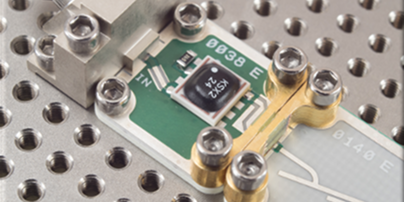
RF design isn’t always easy, especially at higher frequencies. Despite improvements in simulation tools, there’s still no substitute for prototyping and trying out different things. That wasn’t so bad when that meant nailing some nails in a piece of wood and wiring up discrete components. But at today’s microwave frequencies and with today’s IC packaging that simply doesn’t work. Solving this problem is what drives a company called X-Microwave. They have a standard grid pattern PCB for a wide range of RF circuits and accessories to tie them all together. Probably the best way to get a feel for the system is to watch the simple video below. There’s also a free simulator tool worth taking note of that you’ll see in a bit.
Before you get too excited, we’ll warn you that while this stuff is cheap if you need it, it isn’t an impulse buy. The baseboards and probes (the connectors) run from $150 to $300. You can get kits, too, but a bare-bones two-port system is going to start at about $550, which is about $100 off the component parts and includes some extras. Then you need less expensive parts to make the boxes around things if you need them. Oh. Then you also need the PCBs which are not cheap, either. Their prices vary widely as you’d expect, but — for example — we saw amplifiers as low as $80 and as high as nearly $1000. So a complete system could get pretty pricey.
However, if you really need to breadboard RF circuits in the microwave region — they claim the system can get up to 50 GHz — these prices are not unreasonable compared to what you are going to have to do otherwise.
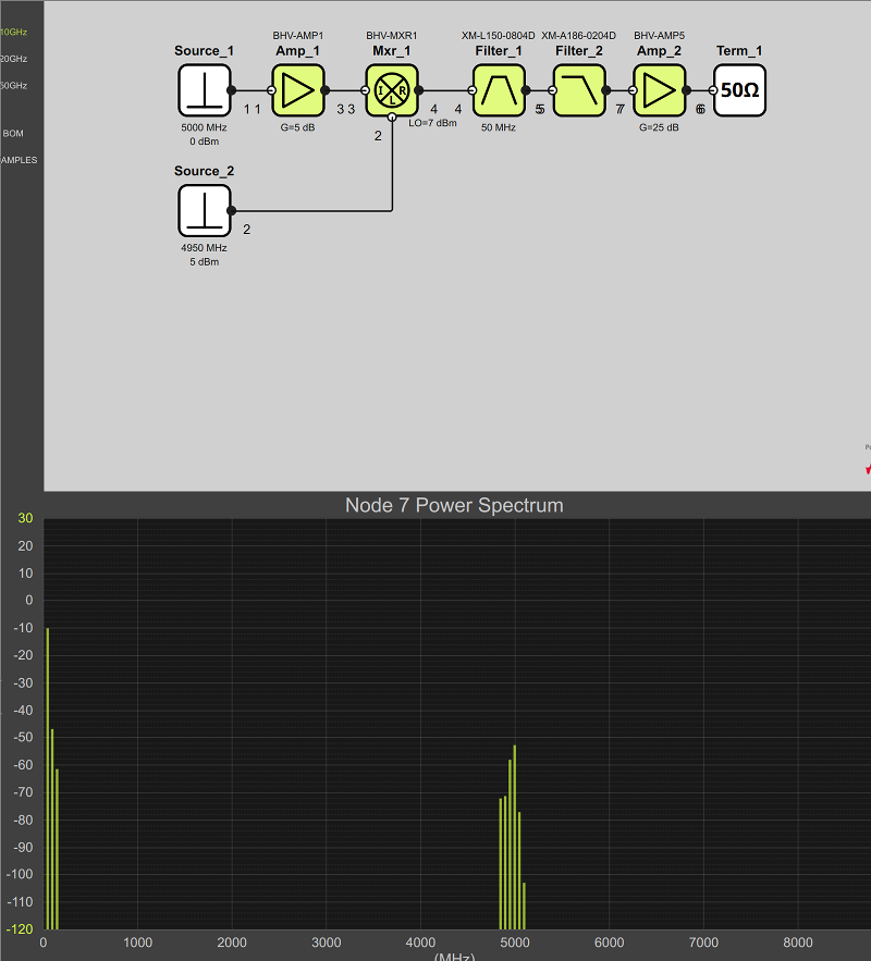
Also, there is a free browser-based simulator you can experiment with which is quite powerful. You do need to register (and while the registration appeared to fail, it actually worked). The backend to the simulator is Genesys Spectrasys, so this is actually a cheap way to get limited access to a very powerful RF simulation tool. It took awhile to figure out, but you can populate the spectrum display at the bottom of the screen by right clicking on any black wire. You can pick behavior models which are ideal or modules that correspond to real-world X-Microwave modules. There’s also an online layout tool for planning your circuit layouts, but that’s not as exciting as the simulator.
This is one of those things that if you need it, it is affordable. If you don’t, then it is priced astronomically. However, it isn’t hard to imagine homebrewing something similar, especially if your frequency needs are more modest. We might suggest the RF Biscuit as a starting point. If you are just too cheap to go this route, you might look into foil tape. We’ve built entire transmitters and receivers using foil tape to create ad hoc “circuit boards.”
Thanks to [RoGeorge] for mentioning this system over on Hackaday.io.


I’m not an RF guy, that looks cool.
What is the second module in the video, the one with the diagonal slashes?
I didn’t hear anything while playing the video, does it have sound?
Although, I wonder if just building a one piece circuit from the building blocks (as shown in the video) is much longer than necessary.
Do the blocks also have differential (input/output) options?
That second module looks like a stripline bandpass filter.
https://en.wikipedia.org/wiki/Distributed_element_filter
What witchery is that?
B^)
(Oh, yeah, thanks for the link!)
Electrickery!
All high frequency stuff is absolute black magic to me
On of my assistants used to call the FT-NIR chemometrics system “Voodoo” and IR and higher with basically pattern recognition models isn’t really that complicated. Tera-Hertz on down to above UHF does seems like a different world though might be more like the physics of IR and higher. I need to read into Bose work more and see what his apparatus are doing. I wonder if he was hacking the human body and not just plants also?
Yeah… looks like a IR-Vis-UV spectroscopy apparatus with different emitters and detectors to me as well as unique materials for the frequency range of the system kind of like using KBr or NaCl salt plates instead of glass or quartz windows for Mid-IR: https://www.cv.nrao.edu/~demerson/bose/bose.html
Yeah, I agree BPF for sure…the range is a little more difficult….maybe somewhere in the 15GHz range….or 12GHz maybe….hard to guess without knowing the substrate and stackup.
Looks like a filter.
Appears to be a microstrip filter
https://en.wikipedia.org/wiki/Distributed_element_filter
Great article and references The foil tape article really connected some dots, no pun intended, seriously. Now the filters are making sense to me considering the trace characteristics like Kirchhoff’s Laws and the details of antennas though maybe something different to more accurately describe microwaves based on readings I’ve not read into yet. The microwave world of strange shapes is starting to make more sense now in kind of a duh moment… though there are different shapes that are not always observed in antenna designs that are more like electric and magnetic electronics components designed for the desired frequency range of operation.
Interesting ruler with some of those higher frequency PCB component references: https://www.ebay.com/itm/PCB-RULER-RF-amp-MW-SPECIAL-EDITION-Double-sided-Gold-plated-FR4-/201618887592
I am not sure it’s in the home gamer territory: I found a board sold $248 for a chip that mouser sells for $17, and you have to add the bias controller. Interconnect anchors are $10 each.
“up to 50 GHz”
“first-pass design success”
And no full-wave sim. That’s cute.
Absurd claim, but still, a neat idea. Might be useful for college labs, if you don’t want to go the waveguide route (i.e. Festo).
RF design is pretty difficult stuff. You have to look at everything like an antenna and how microwave signals interact with the physical world is so different from “normal” electrical signals that it is probably not something you would want to approach unless you want to dedicate a lot of time and/or money to.
There are probably many ham around theses places that could tell you it’s not that bad.
Also, nothing’s an antenna unless you have the impedance wrong: take a PCB antenna and terminate it properly and it’s not an antenna anymore. Microwave mostly just means you can’t use regular componnents anymore (capacitor leads or plates become too inductive to work as a capacitor and capacity between turns on an inductor may make it work as a capacitor) but on the other hand, you can make them on PCB.
During labwork for an RF course, we used something similar but simpler, it was just a steel plate as ground plane while the blocks were single face PCBs with one magnet on the whole bottom. The connections blocks were some cross or straight patterns of copper tape on a bit of foam which was on the underside of a plastic base with 4 magnets on the feets. The PBBs were cut such as they would be just wide enough to fit between the feets, with the copper tape making contact between the top traces of the different PCB blocks. For ports, we had BNCs on similar PCBs but two sided, with the ground connection beeing made throught the magnet.
The contact were sometime a bit fiddly when not super clean, but once everything was set, it was pretty reliable. I remember using thoses up to 5 GHz only but it would probably be pretty easy to make at home.
I remember the trace width being about the same as what we calculated without taking into account the magnet changing the magnetic permeability around the trace, but maybe they had thinner PCBs than normal to account for that.