In all kinds of engineering, we build on abstractions in a kind of inverted pyramid. Lots of people can, for example, design a system using ready-made building blocks on printed circuit boards. Fewer people can do the same design using ICs. Fewer still can design with components. But who designs the components? Even fewer people. Then there are the people designing the constituent elements of those components. [Learnelectronics] wanted to break one of those abstraction layers so he shows how to make your own wire-wound resistors.
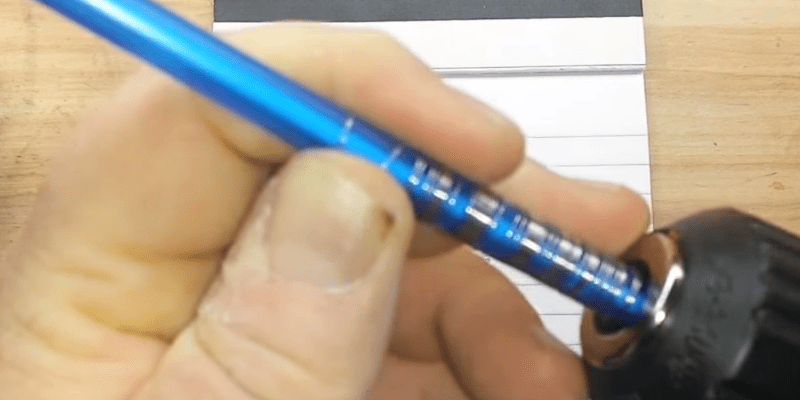
Wire-wound resistors are often used when you need resistance with a higher power dissipation than a common film or composition resistor. Using nichrome wire makes this more practical since a meter of it has nearly 20 ohms of resistance. A regular wire has much less resistance. The video shows a drill winding a coil of wire neatly, but this also highlights one of the problems with wire wound resistors.
Actually, the winding introduces two problems: First, the coils could touch each other which would change the resistance. We would have been tempted to wind with a definite spacing on a form and then epoxy it to the form to give it mechanical stability. He builds his resistor into a plastic tube and does mention he’d pot it if he were really going to use it, but that would still make it hard to get the resistance exact.
The other big problem with a resistor like this is that it not only looks like a coil but it acts like one, too. In some applications that doesn’t matter. But in many, you don’t want the giant voltage spikes that comes with a quick change in current flow. We’ve seen this cause mysterious power transistor failures when a wire wound resistor served as an emitter resistor. In addition to inductance, the adjacent windings give the resistor a good bit of capacitance, as well.
Does that mean you can’t use wire wound resistors? No, you just have to get the right kind. Turns out you need noninductive wire wound resistors that use something called Ayrton-Perry windings. The idea is simple. Suppose you need one meter of wire to get to 20 ohms, but you want to minimize the unwanted inductance and capacitance.
You double the amount of wire and make a 40-ohm resistor with good gap between the coils. Then you essentially wind another 40-ohm resistor in the opposite direction inside that gap (or, sometimes, on top after insulating the first winding). With the same number of turns, the magnetic fields cancel out, meaning there isn’t much inductance. And the adjacent turns of wire have about the same voltage on them, so that minimizes capacitance.
Of course, now you have two 40 ohm resistors, but when you put them in parallel you get the 20 ohms you desire. You also used four times the amount of wire, but there’s no free lunch.
You might think wire wound resistors are old fashioned, but they just went high tech. If you’ve ever used a metal film resistor, these are very similar, but instead of wire, they use a very thin film of nichrome that can be as small as 50 nanometers thick. Usually, they don’t wind these, though. They deposit a uniform film and then use some process — these days, usually a laser — to cut a spiral or other pattern into the film, effectively making it a coil. Yes, they do exhibit some inductance as well, depending on the material and the cut.
We’ve talked about making your own capacitors and even your own inductors. We hope when we post about projects where people bought ready-made components, we don’t get a rash of “not a hack” comments. After all, we stand on the shoulders of giants.


“We’ve talked about making your own capacitors and even your own inductors.”
DIY Quantum dots.
https://hackaday.com/2011/10/12/brewing-up-some-quantum-dots/
Cadmium-Selenide QD production, while relatively straightforward to produce, involve toxic and carcinogenic reagants. Definitely not somebody one who make on the kitchen table.
If anybody has a better recipe involving non-toxic or low-toxicity materials, and if possible at room temperature, please suggest!
When I was a kid I made crystal sets with a cats whisker and piece of galena. DIY point contact diodes.
I’ve done the same thing with a carefully oxidized razor blade and a sewing pin. Not exactly reliable, but I was able to hear the local AM radio station with it.
Ohms/length really depends on the wire gauge and the alloy…a lot of things are becoming harder to find these days due to reduced demand – often the big customers can just buy what they want pre-made. But you can even find exotica like .5 mil tungsten/rhenium wire as new-old stock, Ti wire (heck that’s at McMaster, as are multiple sizes of NiChrome) various sizes used for Vapes, but those tend to be thick/low resistance…
And then there’s the form, and avoiding shorts between turns. Sometimes the normal oxide layer on the R wire is enough, sometimes it’s better to space wind – I find my lathe in threading mode with an obvious jig I made does this well. But usually the point of a wirewound resistor is to handle some dissipation, so any plastic and/or potted form isn’t going to do the job for you. The old school stuff was wound on ceramic tubes that were then glazed like pottery (hmm, is that were the idea of potting came from anyway?).
Terminating the ends of a wire that won’t take solder can be interesting as well…gas tight crimps come to mind.
Common wire wound resistors are normally bifilar wound to reduce inductance.
They’re wound with nichrome (nickle chromium) so if you even need some nichrome you can find some in the junk box. It good as a heater for things like hot wire cutting but it expands (in length) quite a lot when heated.
Speaking of making your own inductors, has anybody here experimented at all with making their own ferrite or powdered iron toroids? I mean the cores themselves, not buying cores and winding the inductors or transformers. In RF designs, the most expensive components tend to be the ones requiring cores, and even small cores appropriate for balanced mixers cost in the $0.50 range, if you can find them.
There is a recipe here to make molded cores without a press that could serve as base for the experiments:
https://www.instructables.com/id/Make-your-own-Ferrite-to-improve-magnetic-fields/
However, it´s probably a lot of refining and measuring and testing to validate the design for RF. The time you would spend on that is probably not worth the price of commercial cores, but if you come up with low-tech a working recipe, that could probably benefit many other people for their custom designs.
The key is in the testing and validating a refined recipe, which might be very tricky with off-the-shelf materials whose composition may slightly vary between different batches.
Try and tell us!
Yes, I understand that it would take a lot of experimenting, and I’m not that versed in ceramics to begin with. In fact, I was thinking of trying a powdered iron in epoxy (mix iron filings into each part of pre-measured epoxy A and B parts, until it’s a thick paste, then mix them together), and I think I have the skills it takes to characterize the resulting compound, but I thought I’d ask here, first. The guy who wrote the instructable apparently didn’t have a way of testing his compound, but one of the commenters tried it and found that it only gave him about 1/10 the inductance of a commercial core, for the same number of turns. Maybe I’ll do this as a hackaday.io project. It just seems like transformer and inductor cores are way overpriced, and if an even half-way effective compound could be made easily, it could be worth the effort.
Maybe, or at least an education as to why they’re the prices they are.
It’s all the setup. The material is dirt cheap, as we found when needing a bunch (well, it seemed like a lot to US) for a product. The guys that make the cores need to do some expensive tooling, but then a tractor-trailer load costs them not much more than the same amount of dirt. If you only want a few thousands, well…they still have to make that tooling. If the market only wants a few millions…same deal. What you are paying for is the half billion they didn’t sell and might never sell. In our case, one of the big’s salesmen formed a little company to buy a lot and sell it to us marked up to that .50c range – they cost him less than a penny, but…$bigcorp had no way to retail such small numbers as mere thousands.
Back in the day I had similar experiences with fluoinert and photoresist (which was then mainly sold in 50 gal drums).
There was just no way I could get an ounce or quart (others lied about the size of their eventual demand and got free samples, but I didn’t want to play that game). Finally someone took pity on me so I could get these things and learn what I wanted to with them.
I further learned this as an inventor – machine shop prices seemed outrageous, so when I became fairly successful and had some land and some money, I built a middling decent shop of my own to do prototypes – annnnnd – it’s all setup, once you’ve got the machines (including mine which were all pre-cnc – which has its own setup and learning curve too) set up – you may as well make 100 parts at least while having beer and mostly just watching. Shops hadn’t been ripping me off at all…even quoting some of my silly jobs turned out to have been an act of mercy.
We used to do this all the time … If you need a precision resistor no need to spend out the ass … Grab the appropriate wire, a ceramic dowel, a precision resistance meter and have at it
Great for purely calculated resistance values without the need for a very drifty pot also
(Note wirewound resistors are not good for all situations … Just had to say)
“you used four times the amount of wire”?
If you only have one kind of wire at your disposal. Four times the amount of wire also gives you four times the wattage.
I’m not sure what you are getting at. The 4x number is because to make a resistance of R you have to create two separate resistors of 2R ohms and effectively wire them in parallel to get half of 2R which is, of course, R. The two windings are set up to cancel each other out magnetically(inductance) and reduce the potential difference between windings (minimizes capacitance). But you still get parallel resistance which means each has to be 2R, or 2X the length of just “ordinary” R and then you are building two so 4X the wire.
I get your point. I was thinking of “amount” versus “length”.
Sorry for the nitpicking.
You can also put the two windings in series—wind a pair of wires in parallel, and connect them together at one end, using the two wires at the other end as the connections to the outside.