Off-the-shelf components are great; the world and our work simply wouldn’t be the same without. But one of the constraints is that one has to design around them, and that’s what led [Antonio Ospite] to create a parametric design in OpenSCAD for a 3D printed holder which snugly fits a number of magnetic spheres around its diameter.
If that sounds a bit esoteric, it will become much clearer in the context of [Antonio]’s earlier work in making a DIY rotary encoder out of a ring of magnetic spheres. He found that such a ring in front of two Hall effect sensors was low in cost, high in precision, and thanks to 3D printing it also had a lot of potential for customizing. But hampering easy design changes was the need for the spheres to fit snugly around whatever shape was chosen for the hardware, which meant constraints on the encoder diameter.
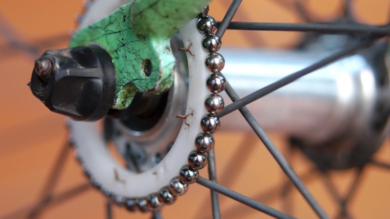
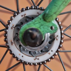
In this case, [Antonio] wished to create an encoder that could be attached to a bicycle wheel but needed to know what outer diameter would best fit a ring of magnetic balls perfectly, given that the balls were each 5 mm. OpenSCAD did the trick, yielding a design that fit the bike wheel and spokes while perfectly nestling 38 magnetic balls around the outside edge with a minimum of wasted space.
OpenSCAD is a CAD program that’s really more like a programming language than anything else. For those who are not familiar with it, [Brian Benchoff] walked through how to make a simple object in OpenSCAD, and [Elliot] has sung the praises of a few advanced functions. Now that this project makes DIY encoders easier, perhaps they could be used to add intuitive new controls to OpenSCAD itself.


I would still want an outer retainer ring to keep the magnets from getting bumped/flung off.
Glue
Seriously! I would not trust that to stay intact at high speed. I think we might be missing some project context…
I too thought that some retaining mechanism might become necessary, but I decided to try without first.
And I was nicely surprised to find out that the magnetic field is strong enough to keep the spheres tight in place even on bumpy roads, downhill, at moderate speeds.
The fact that the spheres touch one another (the holes are smaller that half a sphere) contributes to that.
The sensor is going to be used at low speed anyways so for the final project so this is not a big concern and this solution it’s more then good enough.
But someone could grab your bike by the balls and steal them. A cover ring that snaps on over the balls would be a good thing.
In which our hacker hero boldly looks up a formula, fearlessly types it into a cad program, and heroically 3d-prints the result.
What a hack!
The main merit of this approach is that it is incredibly low cost.
I agree it’s not a great technical hack, I documented it on my blog as a curiosity because I had never used OpenSCAD before, and it’s a nice example of use.
FWIW I didn’t submit it to hackaday tip-line myself, others found it interesting enough to publish it.
This is _exactly_ the sort of thing that’s trivial with OpenSCAD, but requires some real thinking when done with other modelling tools. Yeah, it’s a simple example, but sometimes the simple examples are clearest.
And we think the bare-balls sensor element is cute. And if it turned out not to be sufficient, [ao2] could pretty quickly whip up a thin retaining ring to hold them in place.
Meh. Haters.
I don’t get why hd would need that many magnets? Depending on the counter used in the speedo or odometer there is a minimum speed and a maximum speed that can be detected with a certain number of magnets. Having 50+ magnets gives him very high resolution like 0.01 MPH but a very low top speed unless he wants to use a 24 bit counter or similar.
I would think leaving one magnet out (empty space) would provide an indexing reference such as wheel position.
Not important for a bicycle wheel, but a lot of current engine rpm sensors provide an index on the crankshaft to help calculate crankshaft position.
Made from a different material.
Yes, a magnet and a hall effect sensor ;)
Keep in mind that I wanted to reuse as much as possible stuff that I already had, and the spheres I had were 5mm in diameter.
To have something I could mount easily on the spokes I was constrained by a minimum radius which result in a lower bound on the number of spheres (more than strictly necessary maybe). This is acceptable because the sensor is targeted for low speeds.
when working on projects, always look for solutions that could be easily adaptable to your solution (like crank trigger wheels):
https://www.diyautotune.com/shop/sensors-data-logging/trigger-wheels/
This is something that has been solved many times over, also given its use case it would be better to use a tried and tested solution that works in dirty environments. I get that this may be made from things lying around, but it would be just as easy to find a sheet of ferromagnetic material to cut out a toothed wheel and use an automotive grade sensor. This would remove the failure mode of the magnets becoming dislodged through vibrations from riding the bike.
For a project when I was in college, we cut the teeth into the outer diameter of the brake rotor to measure wheel speed. It greatly simplified packaging, reduced the number of additional components to add, and the brake caliper made a great place to attach the hall effect sensor and keep it in position/alignment.
that’s a hack!
I like that.
BTW my old Bianchi does not even have disk brakes. :)
I wonder if you couldn’t use an inductive sensor (a magnet to go with that Hall sensor, or even just a magnet and a coil) and detect the bike’s spokes directly — no added parts.
But that makes me wonder why no bike computers do the same, and why they instead always clip a magnet onto the spokes, which suggests that maybe there’s more to the problem than meets the eye. My guess is that the spacing required is too tight.
https://www.electronicproducts.com/Electromechanical_Components/Hall_vs_VR_Which_speed_sensor_is_wrong_for_you.aspx
https://www.instructables.com/id/Magnetic-speed-sensor/
I guess it is because a hall sensor needs active power to work. The classic designs use a magnet and reed switch which has practically zero power. You also want your computer not to drain the battery while it is idle, right?
Of course I agree that there are more robust solutions, here I wanted to explore something new while keeping the cost as low as possible. As you guessed I already had the spheres and the hall effect sensors available.
I would say almost any 3D-modelling program would handle that design challenge easily (and most likely even more easy than OpenSCAD). Heck, I think you could even do that quite easily in Freecad (without using the OpenSCAD plugin, of course).
This is perhaps the least notable thing anyone has ever done with CAD
I am the author and I agree. :)
It was the first time I used OpenSCAD and I documented it as an example of use.
That is not true! I made a cylinder with a cylinder hole in it (four times) to make a table slightly taller.
Wow! Some of y’all need to go on a low-sodium diet. Some of us actually like hearing about simple hacks that anyone can do. Personally, I’m far more likely to need to mount magnets on a cylinder than draft a PCB from old photos.
A simpler option could be to use a stationary magnet and hall effect sensor, mounted on the bike frame adjacent to the spokes. The spokes passing in front of a magnet might then induce a change the hall effect sensor could pick up.
Yah, that’s how the steel tooth wheels on vehicles do it isn’t it? Have a magnet so the reluctance kicks back a field the hall sensor picks up.
Bike computers are like that.
I suggested pretty much exactly this in a forum a few days back for reading the teeth on the drive wheel of a PNP tape feeder, but as a differential signal between two hall sensors read in analog mode to get sub-tooth resolution.
Pretty much everything of substance I’ve built in the last few years has at least one thing which was made in OpenSCAD in it. Proper human readable version control, for hardware. Gotta love it.
Speaking of which, my current project was entirely done in it: https://hackaday.io/project/45404/log/151983
Are the spokes wide enough to cause a change which can be measured reliably? It would be interesting to measure indeed.
Using the spokes for direction would be a little more convoluted tho as the two hall effect sensors would have to be mounted distant from each other, or at least at an angle if mounted near to the hub.
That’s a seriously high-resolution encoder. What’s it for? A spoke pov display maybe? Ultra-accurate low-rpm speedometer? The hall effect sensor in my motorcycle’s ignition system is a lot simpler. Just wondering what’s in store!
https://ao2.it/139
You have a ready rotating magnetic field. It remains to install one or more fixed coils and you will have an energy generator to power the electrical system of the bike. And the magnets are filled with epoxy to protect them from dirt. It really will be cool!
Love it! You could increase the resolution by moving to 3mm spheres:
https://www.banggood.com/216Pcs-Per-Lot-3mm-Magnetic-Buck-Ball-Intelligent-Stress-Reliever-Toys-Colorful-p-1204821.html?rmmds=search&cur_warehouse=CN
Ah, I didn’t know there were 3mm spheres, good to know.
However this design was inspired from what I already had: a Tetramag toy.
If I were to design something from scratch I could even use 1mm magnetic cylinders and keep them in place with glue on the 3D-printed part.