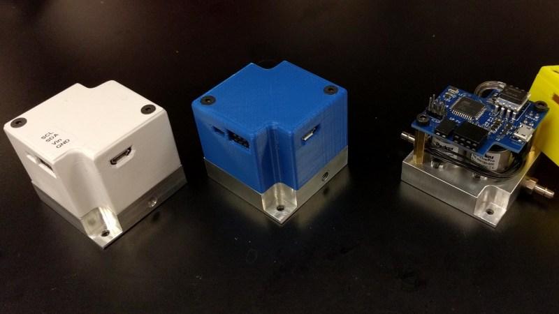
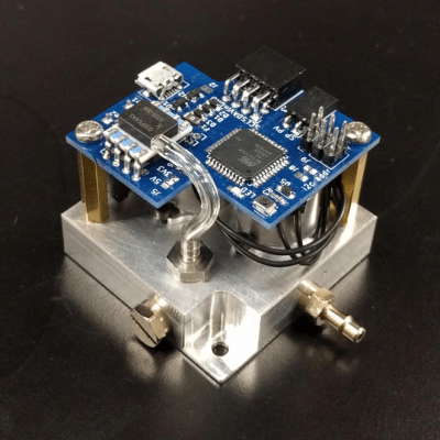
 For many projects that require control of air pressure, the usual option is to hook up a pump, maybe with a motor controller to turn it on and off, and work with that. If one’s requirements can’t be filled by that level of equipment and control, then it’s time to look at commercial regulators. [Craig Watson] did exactly that, but found the results as disappointing as they were expensive. He found that commercial offerings — especially at low pressures — tended to leak air, occasionally reported incorrect pressures, and in general just weren’t very precise. Out of a sense of necessity he set out to design his own electronically controlled, closed-loop pressure regulator. The metal block is a custom manifold with valve hardware mounted onto it, and the PCB mounted on top holds the control system. The project logs have some great pictures and details of the prototyping and fabrication process.
This project was the result of [Craig]’s work on a microfluidics control system, conceived because he discovered that much of the equipment involved in these useful systems is prohibitively expensive for small labs or individuals. In the course of developing the electronic pressure regulator, he realized it could have applications beyond microfluidics control, and created it as a modular device that can easily be integrated into other systems and handle either positive or negative pressure. It’s especially well-suited for anything with low air requirements and a limited supply, but with a need for precise control.


Nice project. I have worked with some commercial regulators (Bellofram units) on professional projects. These have entirely analog control circuitry and mysterious air mainfolds with a voice coil actuator. They work great, but have always been part of a larger system that only relied upon their calibration in a general way and wrapped some kind of external sensor and digital sensor around them in the final system. Typically we were using air pressure to drive a piston and generate force to push on something, and had a load cell to sense force and closed the loop around that. What is being done here looks very high class. We have always had to take great care to filter air and keep debris out of tiny orifices in the valves in the manifold.
External sensor and digital control that is. How many times I have wished this forum had a way to edit submissions.
Now this is a real hack!. Solved his problem by creating/DIYing an improved and cheaper solution. May not still be market-ready but at least solved one man’s problem.
This is a problem not well handled in the market for cost sensitive users. I had a similar need to control pressure in a vacuum tank (deuterium in a fusor), and pretty much all the commercial solutions would be fine for a big lab paying PhD’s to sit around and do nothing while they waited – speed is money for that crowd – those sit-a-rounders aren’t cheap. For me and my fusor…well, I had to create my own, actually fairly similar to this setup, but for far tinier amounts – it doesn’t take much gas to bring a 10 gallon or so tank up to about 1/100th of a millibar, and to regulate a lot finer than that – far less than the initial fill.
To make a long story short, the tiniest lost volume magnetic flap valve I could find – over volted so I could operate it faster, using a arduino for command and timing on the inlet…and a more normal small orifice solenoid valve controlled by the same arduino between the turbo pump and forepump on the outlet, with a high rez a/d on the system pressure sensor…
Arduino commanded by a ras pi, which holds the smarter code, a database, and a vnc server…remote controlled from a PC at a safe distance (my fusor makes rather a lot of radiation).
In concept, about the same thing.
It seems the demand by people with “our size” budgets hasn’t been enough, yet – to encourage someone to make this sort of thing affordable by economy of scale. We can hope – best wishes to [Craig].
Before someone says “mass flow controller” – I use very approximately .3cc or less at STP per entire run of a pretty expensive gas – that one has to satisfy all kinds of regulations to even buy (DEA! No kidding.). Continuous flow is not in the picture. And oh by the way, nearly all of those flow 100’s of times too much even for use in the shortest pulses one can handle. I need to regulate total gas to ~~.003 CC….not as easy as one might think when other effects like tank wall heating and cleanup are also in the mix.
+1
Fascinating, reminds me of my oldie nucleonic ore flow days, pair of Cs137 beta into iron ore curtain horizontal pair of counters measuring mass flow circa 1980’s Mt Newman mining.
The Sandia labs neutristor then up your alley in few respects then re pulse triggering sporadic fusion.
Add a temperature sensor and then you can do mass flow.
Nice project! One suggestion for even tighter control:
Send the time derivative of the input signal also, this way the controller ‘anticipates’ on fast changing signals since the amplitude of the derivate takes care of this (like sine and cosine).
I’ve good experience with this in hydraulics and pneumatics (low stiffness due to compressibility of air).
Thanks for the suggestion! That’s a great idea. I’m hoping to get a student to work on improving the control, so I’ll add this to the list of things for them to try.