We’re not entirely sure what to call this one. It’s got the usual trappings of a drone, but with only a single rotor it clearly can’t be called by any of the standard multicopter names. Helicopter? Close, but not quite, since the rotor blades are fixed-pitch. We’ll just go with “monocopter” for now and sort out the details later for this ducted-fan, thrust-vectored UAV.
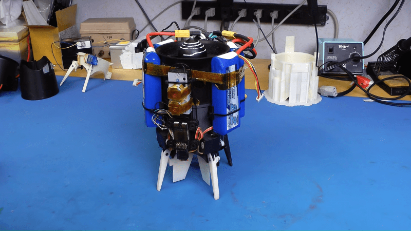
 Whatever we choose to call it — builder [tesla500] dubbed it the simultaneously optimistic and fatalistic “Ikarus” — it’s really unique. The monocopter is built around a 90-mm electric ducted fan mounted vertically on a 3D-printed shroud. The shroud serves as a mounting point for the landing legs and for four servos that swivel vanes within the rotor wash. The vanes deflect the airstream and provide the thrust vectoring that gives this little machine its control.
Coming to the correct control method was not easy, though. Thanks mainly to the strong gyroscopic force exerted by the rotor, [tesla500] had a hard time getting the flight controller to cooperate. He built a gimballed test stand to work the problem through, and eventually rewrote LibrePilot to deal with the unique forces on the craft and tuned the PID loops accordingly. Check out the results in the video below.
Some attempts to reduce the number of rotors work better than others, of course, but this worked out great, and we’re looking forward to the promised improvements to come.
Thanks [Larry] and [Danie] for the tip!


EDFs are spectacularly inefficient at low speeds. Props, and ducted props, work way better.
Isn’t edf a ducted prop? What’s the difference?
I don’t know.
…Then maybe you shouldn’t make that assertion?
Don’t you have homework to be doing?
EDFs have more blades than just ducted props, judging from looking at pictures on the internet.
An EDF is just a ducted prop, but they are optimised for higher speed, not static.
Normally you want a large low speed prop for higher efficiency, not a small high speed one.
Also terribly unstable inverted pendulum. The trick is to get all the weight high up, and far out from the control surfaces. A battery ‘pod’, at some height above of the EDF’s intake, might achieve this.
Keeping the gyroscopic centre at the centre of mass is most important. There is no pendulum to control (google pendulum fallacy), but increasing moment of inertia is a good idea to ease controllability. That would suggest pairs of batteries on sticks, but in practical terms putting anything above and below the fan would destroy air flow efficiency, and spreading sideways kills the impressively compact form factor. It seems controllable as is so no need to change.
…all that said, I figure a pretty good effort to control a very short inverted pendulum. Quite like balancing a 2-inch long pencil on your finger tip, as opposed to a 3-foot long rod. Lots of nasty torque effects too I imagine, from an EDF that would as much like to twist a column of air as thrust it.
Particularly on the control systems engineering, very well done!
The key value here is impressively compact form factor, but if you want to trade high speed performance and medium speed maneuverability, you could use a lifting body intake like the experimental flying saucers. Just a wide, gently curved rounded top where as the air flows onwards towards the intake it follows the curve and therefore generates lift. It works very well but acts to cancel out lateral airspeed, so if you try to go sideways through the air (or stay put wind) the airflow is faster inwards on the upwind or forward side, so generates more lift, and this angles the craft, making it accelerate downwind or slow down. But it can have a huge impact on efficiency so worth a look.
Gadzooks!
The thing resembles the simulator the government had built to teach the astronauts how to fly the LEM. I say resembles because even that thing was extremely ugly and flew far worse then anything we have today, even worse then the birds being built and forced on us by Airbus.
In fact only one survives if at all, they had two built, and sadly one of them decided to commit itself to the ground, the pilot at the time, I believe it was Grissom, ejected.
Does he provide a list of what went into it?
No it was none other than Neil himself. A strong reason why he was chosen for the first landing. He had MUCH more time in the machine than any other pilot. And you can see in the videos of that event that he ‘was committed until he wasnt’ as in, he was committed to trying to stabilize right until it was clearly not possible, and made no hesitation to eject. There was no delay in his decision making process. Nothing like “I think I can..” only “can/can’t”. Very binary. Some men have ice in there veins. Neil had icebergs.
It’s like a much smaller version of the RQ-16 T-hawk drone, that’s pretty cool.
Fantastic! And shivering also as its noise remembers me a dental drill!
Would it make sense to print static vanes into the duct that would redirect the outflow air to provide a torque to counter the spin of the fan/motor? It looks like that’s the first thing the vectoring fins do anyway.
The torque issue is that the fan is acting as a gyroscope, spin isn’t so much of the issue.
Perhaps a pair of counter-rotating fans in series? Not only do you remove the need to re-calculate the steering vector to account for gyroscopic precession (which I don’t think they accounted for RPM at the rotor, which can vary the force?), changing the speed of the two motors would allow for some ‘in place’ steering. That steering while hovering vertically could be very useful to steer a camera.
That’s already been tried by someone. Too many of the controls effected each other and it was even more uncontrollable. Maybe this set of vanes would have let it work better.
Ivan Miranda? Yeah, his EDF-“rocket” failed spectacularly.
The RPM is irrelevant unless it’s really low. A gyroscope re-directs any force you apply to 90 degrees at infinite RPM, and close enough to 90 degrees at anything above couple hundred RPM.
The important thing to notice is that a gyroscope only re-directs force, it does not generate force, so the force turning the craft in the wrong direction is proportional/equal to the angular acceleration of you turning it.
The angular acceleration is already known because you know how fast the pilot is trying to tilt the craft, so you can apply a counter-force at 90 degrees simply by multiplying your desired acceleration with a constant. When the pilot is holding the stick steady, indicating they want to keep the angle there, your acceleration goes to zero and the compensation is nulled out. When they change the stick position, you measure how fast the input changes and derivate the acceleration out of that.
Except that you forgot about the torque generated by spinning the fan. The motor is spinning the fan in one direction. Action = reaction, therefore the motor is technically being pushed to turn the other way. As the mass of the “aircraft” is higher than that of the fan plus the torque applied by pushing air, the frame will not counterrotate with the same rpm as the fan, but it will spin. The control surfaces at the exhaust all have to be angled in the same direction at a certain angle to counteract the torque.
That hasn’t got anything to do with the gyroscopic effect, and the force is only generated when the rotor speed changes. At steady state, there’s no net torque except that generater by the spiraling airflow, which is easily countered by twisting the control vanes slightly in the opposite direction and should be canceled out by the PID controller.
Besides, if you print out suitable counter-vanes inside the chassis, that cancels out the torque caused by twisting the airflow and you don’t have to take it into account in your control algorithm. The resulting net airflow hasn’t got any twist, so the craft doesn’t spin.
Yesterday it was a bicopter, today it is a monocopter.
So what is going to happen tomorrow – a zerocopter?
HaD has covered rockets (zerocopters) recently as well…
B^)
It’s called a nocopter, and depending on how you count, there will never be one, or there’s gazillions and they were here since the universe came into existence.
If we can get that spider string trick with electric field differentials to work, sure
Electrodtatic hovering is a thing. You just need tinfoil and realy high voltages for miniscule lift.
Wouldn’t it be easier to just build a gimbal system around the fan and have the body of the craft move around the fan instead of trying to compensate for the varying gyroscopic forces?
Using internal combustion (IC) engines is impossible in quadcopters because of their slow reaction in RPM which is absolotely necessary to achive reliable stabilisation. In case of this monocopter the same function is provided by vanes which can react quickly enough while the single rotor could spin with a relatively slowly cahnging RPM at the same time, depending the intended vertical lift or descend. In such a way a long endurance drone could be built with IC engine. What is your opinion?
Using ICEs (Internal Combustion Engines) as main vertical thrust, and other rotors to direct and stabilize the craft is a consideration.
Have you tried looking at how helicopters work?
Using a internal combustion in a quad copter with any kind of thrust vectoring would be quite doable.
It is only impossible if you’re using changes in individual rotor speed to affect changes in yaw. Variable pitch propellers enable the use of IC. See here:
https://www.youtube.com/watch?v=XnP3jTwRPv0
Also, variable pitch props enable some really strange flying!
https://www.youtube.com/watch?v=TnGhEInTXYc
Wow! That’s thinking outside the box!
In the context maybe, but that’s how helicopters fly since their invention.
I meant using a race car.
Owning a flying car may yet happen in my lifetime!
It really makes sense to be thinking about cars when you’re considering how to distribute power from one engine out to four rotating things.
Search singlecopter on thingiverse, been on there for 2 years now (and it looks more like a t hawk too)
Wow… this is great!
Very interesting video, thanks for posting!
He should have a chat with Colin!
https://www.youtube.com/watch?v=soxxPyaAT1k
Tom Stanton did the same thing a while back to make a hovering Falcon 9 model. Pretty neat.
https://youtu.be/_kd64VE3A1c
failed to make it work != did the same thing
I gather you didn’t watch until the end. It’s a hovering craft using one propeller and thrust vectoring to counteract the torque. It takes off and flies. Using a long tube, causing the thing to topple over at landing =! failed to make it work.
it might be counter intuitive, but long tube moving center of gravity above motor is actually a huge help, and then it keeps falling down and barely hovers = fail
It takes off. It flies. It works. The rest is just being difficult.
Great work. I know how hard it can be to build a ducted fan.
https://hackaday.com/2015/07/04/ducted-fan-drone-flies/
For a hovering craft, the other kind of duct shaped as the overside of a wing (trumpet at top) roughly doubles efficiency. Oh, found a picture: http://www.aviastar.org/foto/hiller_platform.jpg
Not sure if this is the same fellow (I am thinking not) but he has done quit a bit and calls them a MonoPhan. Numerous youtubes of his contraptions:
https://www.youtube.com/channel/UC2Z2EHw42p9-gRxrIsL66Mw/featured
Someone PLEASE create a mesh Tardis shell around this! It would just look so much like the Tardis flying around.
That said, I really cringed at the first part of the video where the fan sucks in wood shred. Can’t have been good for the fan even if it didn’t immediately damage it. But I bet a front intake screen would restrict the airflow too much.
I am astounded at the engineering in this. Amazing job.
Wow Great Job !
This would be perfect to make a mr. handy
Can someone tell me about the control program for this machine?