“They don’t build ’em like they used to.” There’s plenty of truth to that old saw, especially when a switch-mode power supply from the 1940s still works with its original parts. But when said power supply is about the size of a smallish toddler and twice as heavy, building them like the old days isn’t everything it’s cracked up to be.
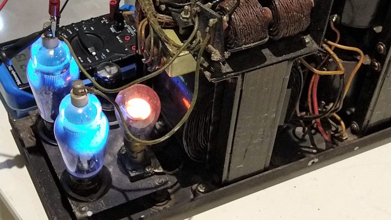
The power supply that [Ken Shirriff] dives into comes from an ongoing restoration of a vintage teletype we covered recently. In that post we noted the “mysterious blue glow” of the tubes in the power supply, which [Ken] decided to look into further. The tubes are Thyratrons, which can’t really be classified as vacuum tubes since they’re filled with various gasses. Thyratrons are tubes that use ionized gas – mercury vapor in this case – to conduct large currents. In this circuit, the Thyratrons are used as half-wave rectifiers that can be rapidly switched on and off by a feedback circuit. That keeps the output voltage fixed at the nominal 140V DC required by the teletype, with a surprisingly small amount of ripple. The video below is from a series on the entire restoration; this one is cued to where the power supply is powered up for the first time. It’s interesting to see the Thyratrons being switched at about 120 Hz when the supply is under load.
Cheers to [Ken] and his retrocomputing colleagues for keeping the old iron running. Whether the target of his ministrations is a 1974 scientific calculator or core memory from an IBM 1401, we always enjoy watching him work.


Oh how I love the glow from a mercury vapor tube.
Many decades ago my dad had a radio p.s. that featured a 5Y3 and an 0B2. Used to love the weird blueish-purplish glow from that 0B2. Now I’m wondering how much of the mercury vapor’s 254nm line makes it out through the glass. Probably oughtn’t have stared at it in a darkened room quite so much.
Don’t worry: you didn’t get any 254 nm light in your eyes.
The envelope on the tube is regular glass (soda lime), which is opaque to those germicidal frequencies of UV.
You would know within a few minutes if you had seen UV-C. In one of the Blade films, the director saw some really cool light blue lights that he had never seen on film before while filming in eastern Europe and decided to use them (a massive array of military spec germicidal lamps) in a vampire autopsy scene, needless to say the actors and crew suffered major vision problems (Photokeratitis) and were in severe pain for weeks after that mistake.
Fascinating! This is the highest power antique regulated supply I’ve seen. Most of the small ones were vibrator supplies, with gas-tube regulators.
But I wonder… There were several other techniques available at the time that would have made this supply much smaller. For instance, they could have used a constant-voltage transformer to provide the regulation. Another technique was a “tap dancer” type regulator; these used a tapped transformer and a stepping relay to automatically select the tap that provided the desired voltage. Another was a motor-driven variac, where the motor was part of a servo loop to regulate the voltage. Still another was the rotary converter; basically a combined AC motor and DC generator on the same armature.
I’m not sure why they picked this particular design. My guess is that because this is a Navy unit, they wanted something reliable without moving parts, ruling out most of your options. There was a “solid-state” unit, using selenium rectifiers, but I think it was lower power.
Selenium rectifiers wouldn’t do any regulation. Most power circuits are pretty tolerant to normal line variation, and a lower power circuit (preamps etc.) can use vacuum tubes or shunt regulators (cold tubes).
so what’s the power output on these puppies ? several kW, dozens of kW ?
In the associated blog, he wrote:
Its power density is really quite low.
Hmm, love to find out the efficiency of the PS. Btw, nice hack!
The power supply is not too efficient, mainly because the filaments in the thyratrons use a lot of power. I measured that the power supply uses 52.5W while pre-heating, 60W while running with no load, and 108W while producing 39W of output (36% efficiency). Based on this, I’d estimate 55-65% efficiency at full load.
I always thought “switch mode power supply” means “high frequency current for smaller transformers/coils”? What we have here is kind of a SCR regulator with thyratrons. That is NOT a “switch mode power supply”.
Sorry for the nitpicking.
I was thinking the same thing. The title initially got me hooked as I was unaware of true switching power supplies being around in the 40s or 50s. I guess using the term switching power supply very loosely it could be described as such, but your description is spot on. It’s an interesting design nonetheless.
You are right, It’s not a SMPS, it is a controlled rectifier PSU
I beg to differ. A “linear” power supply uses an analog control device to act as a variable resistor to regulate the output. A “switchmode” power supply uses an on/off switching device to regulate the output. There’s nothing in the definition to limit the frequency at which it switches.
This design used a 60Hz switching frequency because it was convenient. That required much larger filter components. Thyratrons will switch at much higher frequencies; but I guess they didn’t consider size and weight an issue.
I thought it referred to operating the active device(s) in the switching (saturated) domain, rather than in its linear region. Aren’t the thyratrons either fully on or fully off? Do they have a linear region?
Thyratrons are like SCRs; they are off until triggered then they are full on until commutated. They have a heater to evaporate the mercury, and a fairly large voltage drop across the mercury plasma, so they’re not as efficient as SCRs.
Seeing the schematics : https://lh3.googleusercontent.com/-5SBzfY76hyc/W5H2FJMWBAI/AAAAAAABUKk/kWOaCDRoplUpAGWp1_ufg7CX41mIVon6gCHMYBhgL/w9999/schematic-labeled.png
I no way i call that an smps supply. The tubes act as rectifiers with an feed back controller tube. I see it like an scr controlled one ??
Definition : A thyratron is a type of gas-filled tube used as a high-power electrical switch and controlled rectifier.
How is an SCR-controlled power supply not a kind of SMPS?
A “switch mode power supply” is a kind of power supply with high efficiency and low weight; accomplished with the conversion of the low frequency mains (50/60Hz) in much higher frequency current (several kHz up to the megahertz range). That’s what I learnt in school. Wikipedia and every book I know has more or less the same explanation.
SCR regulated (regardless if primary or secondary) supplies are (in my opinion) a completely different story.
I absolutely love old tech; especially ood tech with mercury, glowing stuff and the smell of ozone inside; please don’t get me wrong about that!
I’m really not seeing any definition under which an SCR-regulated power supply isn’t a kind of SMPS. The only difference is that a “conventional” synchronous SMPS turn on at the same time, and turn-off time is tuned accordingly; given the thyratron this always turns off at the same time, and turn-on time is tuned accordingly.
Alternatively, how low frequency can you go and still have it count as a SMPS? What’s special about that frequency?
In an industrial sense, SCR-RPS are used because TRIACs worked better earlier. (maybe even “still work better at the megawatt scale”, I don’t know). For the amount of power going through them, they do have high efficiency and low weight.
The defining characteristic of a switched-mode power supply is the use of pulse-width modulation to regulate voltage instead of amplitude modulation with a linear element. A switching frequency in the kHz range and up is chosen for desirable properties such as smaller inductive elements and higher efficiency but is not a requirement to be an SMPS. Line frequency “SCR-regulated supplies” like the REC-30 may be an uncommon design today, but the way they operate qualify as switched-mode operation.
It’s a line frequency transformer fed power supply with a switching regulator output.
And how is a “switching regulator output” not a SMPS?
For me, the whole point of an smps is smaller transformers with higher frequency regarding to a linear supply with a heavy 50/60Hz transformer. Maybe by the book a scr regulated supply qualifies as a “smps”; in my opinion, though, it certainly does not.
In my collection of power supply related books (I have a masters degree in EE; so I posess quite a few) a SCR regulated supply is never called a ‘smps’. But I certainly dont want to open a ‘flamewar’ about that issue!
Amazing what can be done with stone knives and bear skins. Imagine if they had 5 or 6 pounds of platinum to work with