
How does a design go from the computer screen to something you hold in your hand? Not being able to fully answer this question is a huge risk in manufacturing because . One of the important tools engineers use to ensure success is Geometric Dimensioning and Tolerancing (GD&T).
A good technical drawing is essential for communicating your mechanical part designs to a manufacturer. Drafting, as a professional discipline, is all about creating technical drawings that are as unambiguous as possible, and that means defining features explicitly. The most basic implementation of that concept is dimensioning, where you state the distance or angle between features. A proper technical drawing will also include tolerances for those dimensions, and I recently explained how to avoid the pitfall of stacking those tolerances.
Dimensions and tolerances alone, however, don’t tell the complete story. On their own, they don’t specify how closely the geometric form of the manufactured part needs to adhere to your perfect, nominal representation. That’s what we’re going to dig into today with GD&T.
Having the Perfect Part Fabricated
Imagine you’re drafting the simple cylindrical part on the left. You would, at the very least, specify the length and diameter of the cylinder. If you’re thorough—and you should be—you would also include the acceptable tolerances for each of those.


The problem is that the cylinder may not end up perfectly round, and the flat end surfaces may not be perfectly perpendicular to the axis of the cylinder. The finished part could match your drawing, but still be ruined by an oblong shape or an angled faces. Even with tight tolerances, your part could end up looking like the part on the right (which I’ve dramatically exaggerated for illustration purposes).
The reason for the potential discrepancy is that manufacturing is imperfect. The part may have been turned on a poorly maintained lathe, which caused the oblong profile. A long cylinder could have been divided up into many pieces with your specified length using a bandsaw, but maybe the blade was worn and it drifted during the cut. For those reasons, it can be important to explicitly state what the geometric form needs to be, in addition to the basic dimensions.
Defining Your Three-Dimensional Form
Like everything else related to drafting, the specifics of Geometric Dimensioning and Tolerancing vary between different sets of standards. But, the general concepts are universal. GD&T gives you the ability to define the three-dimensional form of your parts with various “controls.” Really, they’re just geometric tolerances, but I’m going to refer to them as controls in this article in order to avoid confusion with the standard dimensional tolerances you’re probably used to.
The Circularity (or Roundness) control, for example, would let you tell the manufacturer how close to perfect the circular profile of your cylinder needs to be. If you said it needed a Circularity of 0.01 mm, that means a dial indicator run around the cylinder won’t show a difference of more than 0.01 mm between the highest and lowest points.
As you can imagine, GD&T is a very powerful tool for ensuring that a manufacturer fabricates your parts to your standards. It’s also a complicated one, which is why it’s not used as often as it should be. In many situations, you can probably get away with skipping GD&T. But, you’re opening yourself up to the potential of receiving parts that technically meet your specs, and yet are unusable. That’s particularly true if your design requires precision parts. GD&T protects you from sloppy manufacturing, so long as you know how to use it. So, let’s take a look at some of the common controls you can use.
Types of GD&T Controls
Position
| Symbol: |
Often referred to as “True Position,” this is basically the GD&T equivalent of specifying the coordinates of something like a hole with basic linear dimensions and tolerances. You define the location with linear dimensions from reference surfaces, and allow for some variation with the Position control. In the case of a hole, that variation is a circular envelope around that nominal location.
Not only does Position have more uses than a standard linear dimension tolerance, it also differs slightly in what it allows. A location defined by two linear dimensions with tolerances will result in a square “zone” of acceptability. The Position control, in the hole example, makes that zone circular.
Straightness
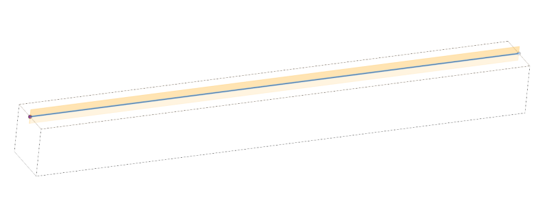
| Symbol: |
The most basic of the GD&T controls, Straightness is exactly what it sounds like: how straight an imaginary line on a surface should be. This applies to only the surface that you call out. If you have a long square aluminum extrusion, this will define how much it can move in and out along a single axis. It can also be used for the Straightness of a part’s center axis.
Flatness
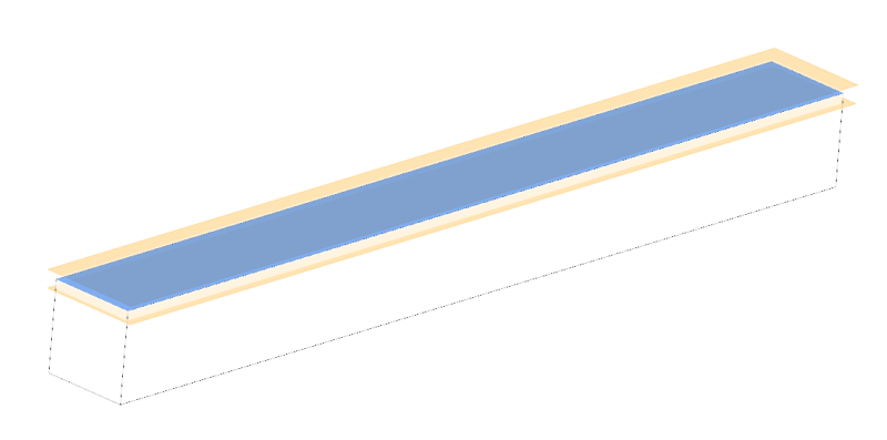
| Symbol: |
Flatness is very similar to Straightness, except that it applies to an entire surface. A dial indicator moved to any position on that surface would need to fall within the tolerance you specify. Flatness is especially useful for machines like mills or 3D printers where the work surface cannot be warped at all.
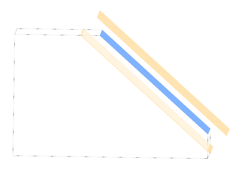
Parallelism
| Symbol: |
This defines how close to parallel two theoretically straight lines should be. If you controlled the Straightness of one surface of your square aluminum extrusion, you might use Parallelism to control the surface on the opposite side. Parallelism is essential for many linear motion systems.
Perpendicularity
| Symbol: |
If the angle between two surfaces needs to be 90°, you should use Perpendicularity. One of those surfaces can be curved on a single axis, like in the case of the cylinder from the beginning of this article. This would let you state that the end surfaces of the cylinder need to be perpendicular to the cylinder’s axis. Notably, this is not an angular tolerance like “90° +/- 1°”, but rather a distance between two imaginary planes that the perpendicular surface must remain inside.
Angularity
| Symbol: |
Angularity is similar to Perpendicularity, except that it can be used with any angle. Also like Perpendicularity, the real surface needs to fall within two planes offset from the nominal angled surface. Angularity and Perpendicularity controls are handled this way so that quality control can check the entire surface using a dial indicator.
Circularity
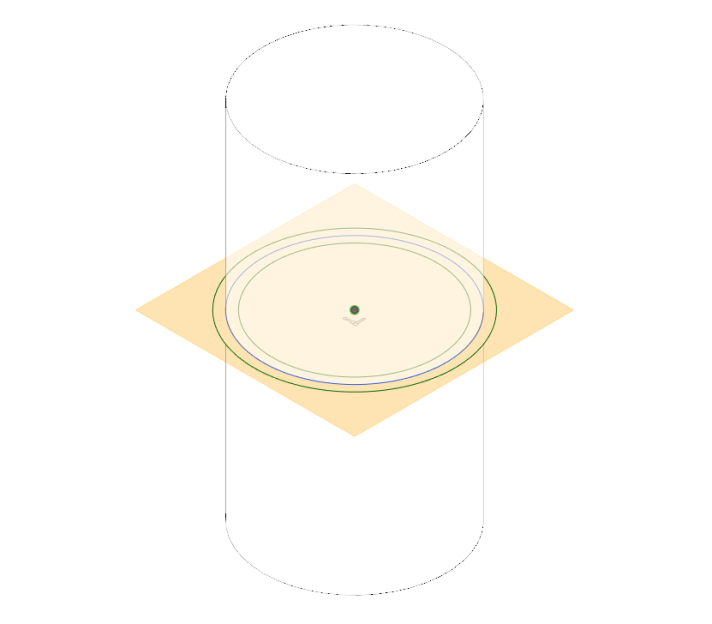
| Symbol: |
As discussed above, Circularity is a control for the roundness of a feature. That may be the outside surface of a cylinder, or the inside surface of a hole. In both cases, it’s a measure of how close the profile is to a perfect circle. It’s important to note that this only applies to a single two-dimensional cross section of the part. This is useful for any round part, but especially those that need roll against another surface.
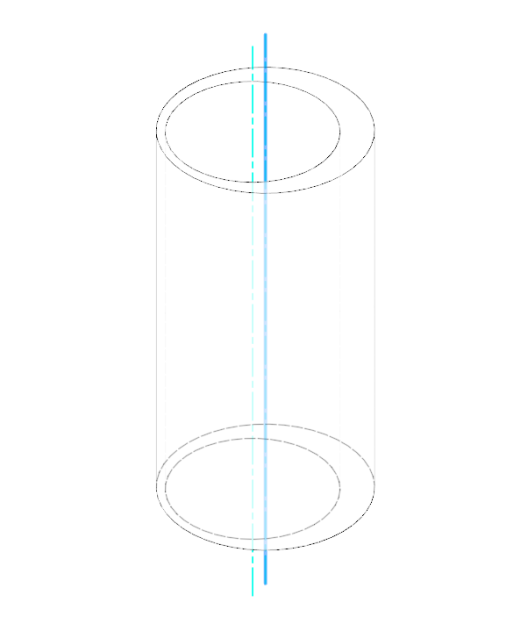
Cylindricity
| Symbol: |
In the cylinder example, what we actually want is a set of GD&T controls specifying its Circularity, Straightness, and the Perpendicularity of the end faces. Because cylinders are so common in manufacturing, Cylindricity covers all of those in a single control. The tolerance defines two imaginary cylinders, one inside and one outside of the nominal, which the manufactured part must fit between.
Concentricity
| Symbol: |
Imagine that solid cylinder was actually a tube. Concentricity lets you ensure a consistent wall thickness by specifying how close the center axis of the inner cylindrical surface needs to be to the center axis of the outer cylindrical surface. If they were far apart, you’d have a thick wall on one side and a thin wall on the other. Concentricity keeps those axes within a distance you provide in order to avoid that. A wheel’s hub, for instance, needs to be very concentric relative to the outside rim.
When to Use GD&T
If you’ve read this far, you’re probably in a state of information overload right now. Implementing GD&T takes a lot of extra work, and it can be difficult to keep track of all of the different types of controls. In addition to the ones listed above, there are other, less common, ones that handle profiles. There are also a couple that are intended specifically to constrain run-out. It can be a lot to wrap your head around, but the good news is that very few people in the real world are expecting you to use GD&T for every feature of every part.
GD&T is just a system for ensuring a part meets standards, and you’re the one who gets to decide what those standards are for your creations. If you simply need to have a sheet metal enclosure for an electronic device you’re selling on Tindie, it probably doesn’t matter if one of the surfaces deviates half a millimeter from perfect flatness. In many industries, even professional drafters skip GD&T unless it’s absolutely necessary.
But, occasionally, it will be necessary, and you should be aware of the basic concepts involved. The next time you draft a technical drawing, take the time to consider which features are important to the functionality of your part. Then, imagine if that functionality were put at risk by unexpected deformities in the geometric form of the feature. If that’s a possibility, take advantage of GD&T in order to ensure that the manufacturer meets your expectations.


“GD&T is just a system for ensuring a part meets standards, and you’re the one who gets to decide what those standards are for your creations.”
Working across large groups, generally someone else.
Also… your audience/manufacture must be able to read GD&T otherwise it is useless an may just add confusion. Sometimes clean simple dimensions mean more than something that has a pile of GD&T overwhelming a drawing. A quality manufacturer will indicate is more open tolerating may yield acceptable parts. i.e. hole patterning. The guy hand marking holes and using a drill press may not be impressed with you gd&t skills.
You skipped the “basic dimension” definition, perfect/ideal dimension with a box around it?
Or how much of GD&T is used to setup a CMM machine for part inspection?
Honestly, if I decided that there was a need to use it, and the manufacturer didn’t know what it was, I would seek another manufacturer, ASAP.
Half the reason for using GD&T is to give the manufacturer as much tolerance as possible but still get a part that meets the required form & function thus making the part as easy to produce as possible. It is a common mistake to assume a drawing covered in GD&T is going to be expensive/hard to make.
Now that we know how to specify our tolerances I’d love to see an article that discusses how to decide what those tolerances are.
Does a good engineer know how to calculate exactly how much give each material will have given a specific size and shape and thus know how off they can be before they stop fitting together? Or do they do it by trial and error, make everything a little big then start slowly shaving it down until it fits then keep shaving it down until it is too loose? Or is it just a combination of experience and guesswork?
Those first couple of methods sound like far too much work. The third though, it would take years of making bad designs to get there wouldn’t it? It seems to me that about the time you get good at it it’s time to retire.
It depends on a lot of things. For many standard applications there are standards (ISO/DIN/JIS/ANSI etc) to refer to that will many situations that don’t have very specific requirements.
However, it also depends on what you’re doing. Getting a hole with a very accurate diameter is very simple using tools like a reamer, even with only a press drill. Getting that hole in a location with the same accuracy is a lot harder and would easily require CNC machinery.
In other instances, there are preset standards for standard solutions like holes and axles that need a loose fit, or a friciton fit with a prectable loading capability. (example: https://www.engineersedge.com/calculators/mechanical-tolerances/table_hole_tolerances.htm). Many other parts have similar specifications for diameter/roundness/…
In many other instances, it depends on what the requirements are. Tolerances for a chest of drawers may be a lot looser than what you could handle in the linear bearings of a CNC machine. All of this is a very important part of the field of Mechanical engineering.
If you’re designing a part to mate with a standard part, like a bearing, the manufacturers will usually have recommended tolerances one the part’s spec. sheet or somewhere on the manufacturer’s website.
*on the part’s spec. sheet…
And then another article after that talking about how to achieve them, and do it consistently in a moderately equipped home shop. That is one of the basic things that I sometimes struggle with, precision, accuracy and repeatability.
And then another article after that talking about how to achieve them, and do it consistently in a moderately equipped home shop. That is one of the basic things that I sometimes struggle with, precision, accuracy and repeatability.
You and me both! In my spare time I do a bit of woodworking, and after watching a guy like Paul Sellers, my joints are way sloppy. I think something that really helps, at least with woodworking, is ensuring that you’re starting with nicely planed/squared pieces of wood. It doesn’t matter if your saw cut is within 0.1 mm of where it is supposed to be if the board is warped.
Yes, one of the things I want to acquire (or build) next is some sort of a planer / jointer and a much better table saw. My table saw is a piece of junk. It is the ‘object lesson’ for what NOT to buy. I don’t think it is humanly possible to spend $300 bucks on a worse table saw than the one I ended-up with.
This is all a bit theoretical for one-off’s like most of us will make. The real value of GD&T is for mass production: It will ensure that all parts will work in all devices/machines regardless of when and where it was made. Additionally, it is a good tool to put the blame on the subcontractor (you didn’t make what I asked you to). Usually a subcontractor or manufacturer will not actually use the tolerances that were specified in production, but will only see if the specs of his (CNC)machine are up for the job.
A fun additonal tolerance to consider is equality between parts. If you’re using spacers to mount something on a flat surface you might not care at all whether the spacer is 5 mm higher or lower, but you do want them all to be the same height. This is also a lot of fun for large machine frames and supports…
Making several equal height parts for a bespoke assembly (standoffs for example) is pretty straightforward in many cases, but requires a shift in thought process: many times we are used to making parts one at a time. When making matched standoffs (or die stops ) often it makes sense to batch process all of the parts that need to match.
For example, I surface ground some stops for a punch press die last week. The stop height in itself wasnt too critical (+- .002, which is a country mile on the surface grinder) but all four stops had to be exactly the same height. The solution in this case was to set up the grinder with all 4 stops on the table, and grind them all in one setup. This ensured that all four were the same height, within the geometric accuracy of the machine (which is very good).
Many times I think this method can solve the need for matched sets of identical components, where exact height is less important than part to part variation.
“On their own, they don’t specify how closely the geometric form of the manufactured part needs to adhere to your perfect, nominal representation.”
Sort of – the dimensions with tolerances but no GD&T callouts does define how close the part must be to nominal and if you make your tolerances small enough then you can fully define anything but you make it more difficult than necessary and depending on the part much more expensive. GD&T allows one to open up all the unecessary tolerances and only control the aspects that are required.
If the implied constraints of your dimensions and tolerances will yield a part that is functional and they can’t be relaxed somewhere by adding a GD&T call-out to some detail when don’t add any. It clutters the drawing and won’t make the part easier/cheaper.
Remember, every dimension potentially needs to be measured by the vendor in order to meet the specified GD&T – in general terms, the tighter the GD&T are, the more parts will need inspection, and the more parts will need rework. For example, a cylinder speciifed with cylindricity of 5 thou should be easy to manufacture for any decent machine ship, and will need little measuring and re-work. In volume, you might be looking at 1 or 2 measured in each batch. Conversely, cylindricity specified in tenths of a thou will need a lot more measurement and possible rework to meet the specification. That extra cost might be justified if the component is part of a passenger jet’s landing gear where hundreds of lives depend on it daily and downtime is staggeringly expensive, but not if it’s a stub axle on a skateboard sitting in your teen’s closet.
You need to choose your tolerances carefully, paying attention to those which are critical. Requesting high tolerances where they are not needed are just going to cost you money – potentially a lot of money.
With the prevalence of CNC machining, tolerances have become much easier to hit – the human element has been mostly removed from the per-part process, and now is most important in the per-job process. Get one part correct, and you’re likely to get them all correct. On-machine part-probing and tool-probing allow the machine to correct for tool wear, part positional errors during multi-operation processes and to measure critical dimensions as the part is made, allowing for a streamlined QA process. Making the first part becomes more expensive, but the volume that follows becomes cheaper.
The main value of using geometric characteristics as defined in standards such as ASME Y14.5 is that one is able to be explicit about the relations between produced features and their ideal form and size and to be more explicit about relations between multiple features in a way that conventional dimensions cannot. In a flat plate it may be very important that a hole is perpendicular to one of the faces. Conventional dimensions offer no way to describe which face and how perpendicular. This task is easy with geometric characteristic symbols and a feature control frame (FCF) which specifies a datum reference frame (DRF). A close second is that geometric characteristics allow linking multiple variables together – example: the perpendicularity of the hole can be allowed to increase if the hole is larger and therefore allow a wider range of acceptable parts that will still function.
The downside is that being able to be more explicit comes at a price of being more complicated. One big complication is that analyzing the effects of tolerances can lead to large chains of trigonometric functions and difficult probability summations. It is difficult enough that the software to do such analyses on arbitrary assemblies is both expensive and relatively rare. This also means that most users are ill equipped to do such analyses for any but simple cases, which leads to tons of arguments.
Oh for Pete sake, please stop promoting the use of concentricity. If you read the formal GD&T definitions you’ll find it doesn’t really mean what you think it means. In most cases you are actually trying to define location relative to a common axis, whereas GD&T concentricity is defining the centroid or center of gravity.
99% of the time you really want to use location, runout, or total runout.