When I started working in a video production house in the early 1980s, it quickly became apparent that there was a lot of snobbery in terms of equipment. These were the days when the home video market was taking off; the Format War had been fought and won by VHS, and consumer-grade VCRs were flying off the shelves and into living rooms. Most of that gear was cheap stuff, built to a price point and destined to fail sooner rather than later, like most consumer gear. In our shop, surrounded by our Ikegami cameras and Sony 3/4″ tape decks, we derided this equipment as “ReggieVision” gear. We were young.
For me, one thing that set pro gear apart from the consumer stuff was the type of connectors it had on the back panel. If a VCR had only the bog-standard F-connectors like those found on cable TV boxes along with RCA jacks for video in and out, I knew it was junk. To impress me, it had to have BNC connectors; that was the hallmark of pro-grade gear.
I may have been snooty, but I wasn’t really wrong. A look at coaxial connectors in general and the design decisions that went into the now-familiar BNC connector offers some insight into why my snobbery was at least partially justified.
Keeping the Impedance
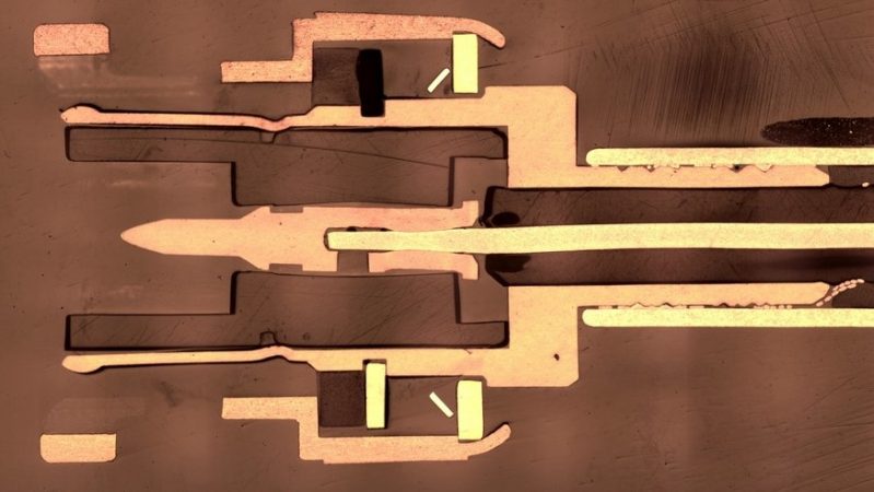
The connector that would eventually become known as the BNC connector when it was invented in the 1950s has its roots in two separate connectors developed in the 1930s and 1940s for the burgeoning radio and telephone industries. When it comes to wires and connectors for DC and low-frequency AC circuits, pretty much anything that will carry the current and provide a firm mechanical connection will do. But once a circuit is into the radio frequency range it’s a different story. At such frequencies coaxial cable is preferred for transmission line, and any connectors inserted into the line need to be engineered to minimize changes in impedance, which could cause reflection of the signal and generate standing waves that can cause damage.
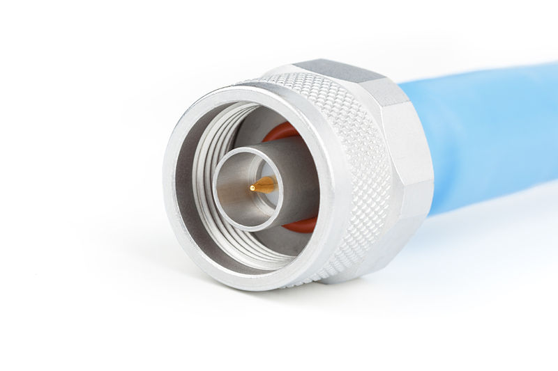
Paul Neil, an electrical engineer who had been with the Bell Company since 1916, was well versed in RF systems. In the 1940s he identified a need for a coaxial connector capable of working well at microwave frequencies and designed the Type N connector. Like all coaxial connectors, it was designed to present as little change in the characteristic impedance of the feedline as possible by keeping the spacing between the center conductor connection and the outer shell as close to the feedline dimensions as possible. Neil’s connector had a female threaded outer shell on the plug that mated with male threads on the matching socket, and was designed to be weatherproof. The N connector took its name from Neil’s last initial and is still in use to this day.
Meanwhile, an engineer at Amphenol Corporation was working on his own design. Carl Concelman’s connector, similarly dubbed the Type C connector, used the same approach to reduce impedance changes in coaxial connections. However, he chose to make his connector quick-disconnect; rather than tediously screwing and unscrewing the outer shell, the C connector had a bayonet connection. The outer shell of the socket had lugs diametrically opposed on its outer surface. These lugs would mate with the long arm of L-shaped grooves machined into the inner surface of the outer shell on the plug. The shell would be rotated to move the lugs into the short arm of the groove, locking the two connectors together mechanically and electrically.385
Best of Both Worlds

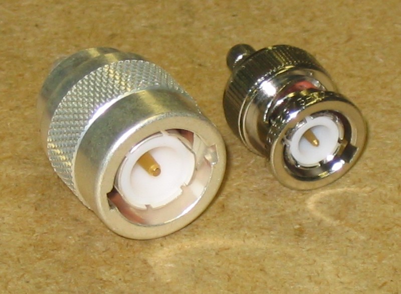
Both the N and the C connectors enjoyed success in the marketplace, but neither was ideal. The N connector was slimmer in profile than the C but had all that pesky threading and unthreading to deal with; the C connector has that nice quick-disconnect but was bulky. In addition, neither connector was particularly easy to manufacture as each required some fairly fancy machining. With those shortcomings in mind, an engineer at the Hazeltine Electronics Corporation named Octavio Salati came up with his own design. It would have the bayonet locking feature of the C connector and the slimmer profile of the N connector. It used the same techniques as both connectors to minimize reflections due to inline impedance changes.
Salati’s connector was patented in 1951 with the unexciting name “Electrical Connector.” Unlike its predecessors, it would not be dubbed the “S-Connector” but, in a gentlemanly gesture, it was called the BNC, for “Bayonet Neil-Conselman.” To support the RF work for which it was originally designed, the connector had a 50-ohm characteristic impedance; later, a 75-ohm version was made for the television industry. The connector is usable up to around 11 GHz, although it’s not ideal past 4 GHz or so owing to the slots cut into the conductor for the outer shield, which start to radiate signals.
The BNC connector has seen widespread acceptance as a coaxial connector in industries far beyond its original target markets. From public service communications to scope probes to computer networking, Salati’s design, and by extension both Neil’s and Conselman’s, has delivered solid performance for the past sixty years.
[Featured images: SMT Analytical, Belden Corp.]


I found hooking up thin ethernet with BNC connectors more aesthetically pleasing than setting up CATwhatever with the overgrown modular phone connectors. Connecting a BNC to the socket is just so mechanically satisfying.
Of course, the downside of Thinnet was that if you got the impedance wrong anywhere along the bus, the entire segment would crap out. The beauty of switched twisted pair (which is just about universal nowadays – “nobody” makes TP hubs anymore) is that each device gets its own segment, so it’s less likely for a single device/drop to impact the rest of the network (it’s not impossible, of course – there are all sorts of attacks on switches that can make them malfunction).
I’ve actually been at at a LAN party where the network was working but a bit on the slow side. I found out that when setting up, they didn’t have a long enough BNC cable to go all they way across the room, so they used RJ-11, affixing it to a T-connector on either side with scotch tape.
I…..honestly respect that lol
Our first network at work was a hodge podge of ThickNet and ThinNet. No one paid much attention to cable lengths. One day we tried to connect to a printer and it just wasn’t “there”. Other nodes had no trouble connecting to the printer, but the node we just added would not. After further investigation, we found many more pairings that didn’t work. We started paying more attention to WHERE the nodes connected after that.
Oh, I can imagine. I confess my experience with thin Ethernet networking was limited to two NeXT computers at my house.
Fun (and probably terrible) fact: Assuming both connectors are 50 ohms, you can press an N-Male into a BNC-Female for a temporary connection. When I was a two-way radio tech, a lot of the techs would keep an N/BNC adapter on the N connector on their test equipment to help prevent damage to their expensive equipment (cross threading, bent pin damaging the fingers of the center conductor, etc). Most of the time a proper BNC cable would be used, but when it was necessary to use one with an N connector, they would just press it into place.
You’re right: It’s terrible, a bad idea, and a serious oversight in the design. Jamming a male N into a female BNC will overstress the female contact. A male N center contact is quite a bit larger than a male BNC contact. It will usually ruin the female for future use with a BNC. (go ahead, make your own puerile jokes.)
It is also a serious oversight that banana peels and peanut butter sandwitches fit in the slot of VHS recorders.
Such actions usually tun the VHS recorder inoperable and also foul the eject system which necessitates a round trip to a repair shop.
I’m sure bologna slices and CD/DVD players don’t mix as well.
My kids used them for a toaster.
Back when I worked in a TV shop in the late ’70s and early ’80s, one of our more common TV failures was caused by kids dropping pennies into the slots on the back of the set. Another common one was kids rapidly flipping the TV on and off rapidly until it no longer came on again…
Interesting, I would have thought to maintain a constant impedance of 50 ohms, the ratio of the inner pin to the outer ground of the female N and the female BNC would be exactly the same size, therefore resulting in the inner pin being exactly the same size on both. If the BNC pin was smaller, then it would have a higher impedance than the N connector. This is the case for a 75 ohm BNC, but a 50 ohm BNC, surely should be the same as a N connector.
I have always wondered how the impedance (quality and other parameters) of the connectors is determined and where I can find some mathematical theory that supports it.
You could always go right back to Maxwell, or even Jackson. But I suspect you’re looking for something more accessible. Any 2nd year university E&M textbook will give you the theory: it’s pretty much introductory material. Horowitz & Hill 3rd ed., appendix H covers the basics.
It’s the same as the impedance calculations of the coaxial feed line. Essentially a relationship of the diameter of the dielectric, the center conductor and the dielectric constant of the dielectric.
To be precise, its (138*log10*(diameter of the dielectric divided/diameter of the inner conductor)* (Er^-2))
So a 75Ω BNC will have a different diameter center pin.
“To be precise, its[sic] (138*log10*…”
Depends on your definition of “precise”. That magic number “138” is just an engineering approximation: it’s accurate to the number of significant figures presented. The OP was asking about the “mathematical theory that supports it.” Peeling back that first curtain of the theory reveals that “138” is real just a good approximation to the actual terms sqrt(µ0/ε0)/2π*ln(10).
It’s some complicated equation of the inductance and capacitance of the cable. Cables have inductance cos they’re long, and capacitance because they have two conductors separated by an insulator. So the particular materials and exact design of the cable decide it’s impedance. For some reason it doesn’t depend on length, I suppose because inductance and capacitance must both increase at the same rate.
Unless you *really* want to know, just forget about it. It’s not simple, and it seems like it’d be completely unsatisfying to know it.
Some RF circuits (eg. Return Loss Bridge) use coax like a transformer: primary winding is the center conductor, secondary winding is outer conductor.
Knowing about inductance & capacitance of the coax probably helps when designing, to determine frequency range.
https://tse2.mm.bing.net/th?id=OIP._x0_rf5lo62gkDPMcGmbCgHaEY&pid=Api
Why 385?
+1 ?
word count in that section, I’d guess… and the copy editor didn’t catch it…
That was the number of words in the chapter, don’t know why they would keep track of that.
What is so special about 50 ohms characteristic impedance that it’s used so frequently? It is simply because it’s “about right” and cables, connectors, etc. are commonly available?
What is so special about 50 ohms characteristic impedance that it’s used so frequently?
https://hackaday.com/2016/07/11/whats-special-about-fifty-ohms/
To maximize power handling capability for a given cable diameter, there’s an interaction between conductor size (for voltage drop) and core-tube spacing (for voltage standoff). The loss curve is actually minimum at around 35Ω, but it’s quite broad. More-or-less 50Ω is the base impedance of a vertical quarter-wave antenna, so 50Ω is nice for that and close enough to 35Ω to still be good for handling power.
75Ω gives the lowest attenuation per unit length for a given dielectric material and cable diameter. It is therefore preferred for carrying signals (not power) over longer distances. That’s why it is used for video and cable TV.
I was once told by a fellow who should know (Bob Metcalfe) that despite the higher attenuation, 50Ω was chosen for Ethernet specifically because the lower impedance made collision detection easier, and, due timing constraints, Ethernet cables cannot be long enough for signal loss to be a problem.
50 and 75 ohms are compromise numbers that balance the voltage losses and attenuation. Depending on the frequency, you get good results between 30-125 ohms, with 50 and 75 getting the best results for transmitting at HF to UHF frequencies.
Nothing like an annoyingly close collection of BNC connectors to ruin your day and your fingers.
http://img.everychina.com/nimg/0a/0c/84afa0923e0efb70fd08fae426e0-600×600-0/hd_analog_video_matrix_system_32ch_analog_tvi_cvi_ahd_or_hybrid_input_8ch.jpg
BNC removal tools weren’t complicated to make or buy and a godsend for such beasts.
Sample image. Matrix of many many channels in good old analog days.
You think that is close together.. you should see the patch panels that I have to work with. They stagger the height of the connectors to pack them much closer than that!
Luxury! Back in the day we used to work with BNC connectors tightly arranged in a honeycomb pattern spaced 1 Planck length apart in a enclosure make of razor sharp cast iron plates that weighed a ton and random connectors would have 400 Volt DC on them which isn’t so bad as long as you were not forced to wear cold wet woolen mittens while being grounded via the scrotum using jumper cables…
And kids nowadays think they had it tough…
Ha. In my day the BNCs were so close together that a singularity formed when all the channels had white test patterns on them and someone didn’t follow through with a subcarrier pulse. Made quite a racket when the ruddy router vanished in a puff of hawking radiation I mean to tell you.
There is worse. The same with M12 connectors !!!
SMA connectors. And a special crescent style socket tool, that slips onto the coax to loosen / tighten the connection.
God help anyone who misplaced that tool.
Back in the day when I work with Analogue TV I remember a 1 In x 10 Out video DA (Distribution Amplifier) in a 3U rack mount module. It had 11 BNCs and a power connector on the back. It was impossible to connect the BNCs without a tool like this: https://www.alibaba.com/product-detail/DW-8048-BNC-Connector-Removal-Tool_60636352643.html
PS I still have a box of BNC connectors, T-pieces, and terminations originally for video & later for 10Base2.
This has reminded me that I once had a complete set of tools for stripping coax and crimping connectors, which has now been replaced with the same sort of tools for making ethernet cables. Stripper, crimper, RJ-45 inserts and lots of boots in different colours. And a cable tester.
PPS Another triggered memory!
When I joined the BBC in 1969, the standard video connector was a MUSA https://www.google.co.uk/search?q=MUSA+video+connector&num=20&newwindow=1&tbm=isch&tbo=u&source=univ&sa=X&ved=2ahUKEwiw-6Li5JXeAhVCat4KHcszDG0QsAR6BAgGEAE&biw=1600&bih=982
This was invented by the GPO (General Post Office) for use in radar. I seem to remember it was a 50 ohm device. All video installations included patch bays with paired rows of recessed MUSA jacks. Cables had sockets on the end. Equipment was connected so that outputs were on the top row and inputs on the bottom with U-links connecting the rows. By removing a link you could break into the circuit and route it somewhere else. The stuff in the linked images is modern and designed for 75 ohm cabling to use with SDI. Modern racks have a BNC on the back. The advantage of MUSA over BNC for patch panels is higher packing density and easy of insertion/removal.
Note that the Wikipedia page claims the inventor was Bell Labs. Not so!
I have seen connectors very much like that (MUSA) on early Bell television gear here in the US. The gear showed up at my school in the early 1960s, having been surplused out by Bell and gifted to us. I suppose it might have been a decade old when I saw it. When was the MUSA introduced?
This connector looks somehow similar to the old big car radio antenna connector.
I saw my first BNC tool like that back at COMDEX (1988 or 1989)
It was almost like dying and going to Heaven!
Needs something like this:
http://www.canare.com/ProductItemDisplay.aspx?productItemID=28
I splurged on a crimper and a box or two of 50ohm Canare crimps.
High quality, and much better performance than the unknowns of ebay specials..
The only problem is I got a bit carried away with the crimper and now I have too many BNC cables and adapters to know what to do with…..
I would like to see an article on the original full size banana plugs and jacks. With metal shells they were nearly indestructible. The wiping action as well as spring-loaded contacts made them self-cleaning as well as very low resistance. Widely used by the military in World War II. Quickly and easily connected and disconnected, yet very secure. Yet, in spite of their many advantages, they are rarely seen on new equipment today.
If I’m not mistaken, the UHF female connector (SO 259) will accept a banana plug.
Son of a gun. All these years, and I never noticed that. I just tried it and you’re right.
I can’t think of a single sensible reason to stick a banana into a UHF socket, but it does fit just fine.
“UHF” are known as “Shielded banana-plugs” by coaxial conneseurs…
They used to be very common on European radio receivers, tape recorders, etc., until sometime in the late 1960s, when it was realized that people were able to stick them into the mains sockets. It didn’t help that the spacing of the holes on the radio equipment were the same 19mm as was and still is used for the mains sockets, and thus the old-style 6A mains plugs with their 4mm pins would fit into these as well, so you’d see them used for speaker connectors, antenna connectors and suchlike when no 4mm banana plugs were at hand. These would of course still fit right into ordinary mains outlets and mis-plugging was known to cause pain and destruction… So towards the end of the 1960s, a number of DIN standards were invented and put into use, making the plugs and sockets all different ones for FM, AM and TV antennas, all 300 Ohm balanced; speakers. record-player inputs, tape deck input and output, when these were not using the American RCA-type connectors.
They remained in use on professional equipment and on equipment such as laboratory power supplies and instrumentation. Variants existed, notably the Bruel & Kjær instruments used a shielded recessed variant, which would also accept the standard simple ones. Other equipment such as signal generators had SO-239 connectors which will accept a 4mm plug in the center, (and usually there would be a 4mm chassis socket for a ground connector next to it) But people that would use this kind of equipment knew enough not plug them straight into the mains.
I had set of Christmas tree lights that had banana plugs instead of a normal mains plug. I don’t know if it was done like that originally, or someone just replaced a failed plug, these lights were older than me. It was really a bad and dangerous idea.
But in that time it was generally accepted, that not every object around us has to be completely idiot proof.
Ahh, the days of walking around with a bunch of BNC terminators in your pocket (and unfortunately nicknamed female-female adapters.)
+1…
Similar to a change jar that you dump change into at the end of the day, I’ve got a box of BNC terminators in the garage at home from emptying my pockets (many) years ago.
I did never get the idea of this “dumping change”. It’s called “change” because you need it to pay the exact value of the bill. If I remove it from the pocket, it accumulates in said jar and I have to deal with it later. I prefer to keep the level of it in pocket low, just by using it regularly.
And I always thought that BNC meant Baby N Connector. Silly me.
Also, we have British Naval Connector and Bayonet Navy Connector (my favorite). Anybody want to do a short piece, with attribution, on the lineage of the BNC acronym? (hint: consider this as one of many potential resources… https://www.americanradiohistory.com/Electronics%20_Master_Page.htm )
You are OK.
I was the silly one. I ALWAYS thought BNC was British Naval Connector … but also always quietly wonder why will the Navy develop a specific naval connector???
All is clear now :-)
I was taught that it stood for Bayonet Nut Coupler.
There’s so much lore that was just flat out wrong when it comes to names in TV production. It’s funny that in a world where so many names get the Xerox treatment (all CGs are Chyrons, etc) that the one that actually is named for someone, no one knows the name of.
Your comment, Lufo, brings out a good point. Acronyms are usually industry specific. You must know the industry or concept for which the acronym applies before you can be certain of what the author is talking about. For example, in the motion picture industry, BNC formerly stood for Blimped Newsreel Camera (ie: the Mitchell BNC).
ACRONYM: Abbreviated Coded Rendition Of Nomenclature Yielding Meaning
B^)
Especially one, which is not water tight. :-)
I recall seeing it listed in a glossary of a (U.S.) military document as Baby Normal Connector
(and I held onto that definition with a tight fist for over a decade -sigh!)
Now if someone would just come up with an industry-standard connector for Ethernet that’s as handy as the BNC ones. As best I can tell, that outsized phone-like Ethernet connector dates from the 1970s and was deliberately designed to make disconnecting hard so users would call in IT staff. I’d love to see it replaced with something as easily managed as the Magsafe connector that used to be on Macs before Apple adopted a policy of not listening to its customers.
A quick disconnect (like mag safe) is sort of the opposite of what you want for network connection interconnects, isn’t it? Think of a switch in a data center. That’s a disaster waiting to happen.
For a quick-disconnect network you’ve got Wifi.
We are switching to 10G SFP cabling in all our racks at work.
They are a *much* nicer connector to work with, and the cables are just stiff enough to not coil like a telephone cord as the RJ45 cables do, but are flexible enough to easily sit nice and neat in the cableways. Slightly thinner than Cat6a too.
I do not see why a RJ45 is considered hard to disconnect. The drawback of this in meeting rooms is, that the locking tabs often break, especially when you have several of the cables in a bunch and try to pull one through. The protective tabs do not really prevent this.
Don’t forget the telecom use of 75 Ohm BNC on connections like DS3.
I have the same feeling about connectors for digital pianos / synthesizers. When there is an IEC connector (for the internal power supply) it typically isn’t rubbish. When it has XLR connectors as well (for balanced audio) things couldn’t be better.
Before broadband internet access, I remember my neighbor friend and I wanting to connect our computers with 10BASE2 coax. The max cable length woulda made it work. Never got around to it though.
My grandfather always had this weird shaped thing in his pocket that said “tuit” on it, and whenever someone said they’d “do something when they got around to it” he’d pull that out and be like “Here’s your Round Tuit, now go get ti done!”
You have to be sort of careful doing that sort of thing – you don’t want the coax shield to connect the grounds between the two premises. Nowadays, even for short runs to out-buildings I would just use fiber to make sure there are no issues with either ground loops or potential differences (but, of course, it’s much cheaper now).
Like the dictum that 10Base2 (Thinnet) requires exactly one terminator at the end of the line, it explicitly dictates that the coax must have at most one ground point (typically the hub end). DEC, in particular, was pretty good about providing insulated BNC connectors and terminators so accidental contact with ground would not happen. Every 10Base2 NIC adapter card has an isolation transformer and that signature isolated BNC connector specifically to provide that ground isolation.
Friends of mine did exactly this. Worked quite good. But I think once they had some dead network cards due to indirect lightning.
Really enjoying this series so far, and looking forward to what other topics you look at.
Ideas off the top of my head:
The various fiber optic plugs
USB
HDMI
Sim Cards
The U-law telephone codec/algorithm
The Multimeter
XLR
phone cable (1/4 inch plug)
SATA
Smart cards, and the chip in modern credit cards
SIM cards and smart cards are more or less the same topic. On that subject, there ought to be a mention of the DirecTV people suing hobbyists who buy smart cards and equipment regardless of whether or not they intend to attempt to fraudulently obtain service “just because.”
may I suggest the DC barrel connector? A connector that’s ubiquitous for supplying power to all sorts of gadgets, but doen’t even have a really well-defined name. Where did it come from? Who made the first one?
and now for the dishwasher: I have aBNC like connector on my HP 1600A logic state analyzer, slightly smaller, with three notches around the shield. any idea what that one is called and where to get it?
Is that actually a triax plug? Triax is used when you need a “driven shield” for absurdly high-impedance signals.
Here’s a hi-quality picture of that (see lower right corner, “TRIG BUS”)
http://dustyoldcomputers.com/pdp8/images-3C8F62C8/R00000291-hp.jpg
That would be a triaxial connector. I encountered them on some Hewlett Packard precision equipmen a long time ago. They still exist, searching for “triaxial bnc” in Google brings up pictures,and references to digikey and other places where you can buy them.
Don’t forget that there’s also a TNC connector. TNC stands for threaded Neill-Concelman. It is essentially a threaded version of its bayonet cousin, the BNC.
Getting back to 1980’s video, for a practical 6 foot run of 75 ohm cable it doesn’t matter spit what matching impedance the end connectors have. For that matter, its a niggling personal, or manufacturer’s, preference to use ‘F’, BNC, or RCA connectors. (sir, would you like your connectors gold plated, and that cable oxygen-free?)
Not much practical difference at low frequencies between the F and BNC, but the RCA have no locking mechanism and very low contact force on the shield.
The RCA have another drawback: GND/shield connects second after signal. If you have a GND differential voltage between devices, e.g. by Y-capacitors in ungrounded equipment, you can easily damage input amplifiers. Had to repair already some mixing consoles due to this damage.
It sure as hell does for pro video. First, that run is as likely to be 60 feet as 6. Second, it’s not just that six foot run. It’s that six foot run from your source to a DA to a six foot run to a TBC to a one foot run to a mixer to a one foot run to another DA to a six foot run to waveform monitor to a twelve foot run to a destination. And that’s a simple path for pro video. Those impedance mismatches start turning into practical problems in a hurry.
That’s the classic, rational, argument used to justify not mixing 50 ohm cables in 75 ohm systems, or introducing some odd termination value (or lack of one) at the end of a cable. It isn’t operationally valid when speaking of connector impedance mismatches in SD video systems..”Pro” or otherwise.
In other words, you’ve never worked with a good chief engineer who can show you the difference between a good and a bad signal.
I already know that you are FOS talking about SD video systems “pro or otherwise”. A good SD system was pushing 1200 horizontal lines of resolution (an analog equivalent of 2400+ x 480) and to dirty that up by being a dumbass using a the wrong cable makes you an epic dumbass who should never be allowed near the kind of gear that can push that resolution.
I’ve seen my fair share of deceptive snob puffery come and go through the years, yours being a good example.. 2400×480 isn’t SD video, nor was 2400×480 a resolution suggested by the original conversation.
Analog video didn’t have pixels. Resolution was measured in horizontal lines of resolution.
Have you ever asked yourself by the DV video standard (which was considered a prosumer format for its low resolution) used non-square pixels at 720×480 for 4:3 video?
First it must be “vertical lines of resolution” (equivalent to horizontal resolution).
Second, that would be about 20MHz of video bandwdith. Something you never really had in any color broadcast, think of the color subcarrier frequency of 4,43MHz or even less in NTSC.
You can easily be dealing with 20 mhz of bandwidth on coax in the studio. You wanted to have the highest quality video behind the transmitter because it is going to have to be compressed down into that carrier bandwidth (on top of all of the generational losses that you are going to take in the connections between all the gear — which you minimize by being careful about impedance matching.
RCA is obnoxious because the center pin mates before the shield/body/ground, which is generally terrible practice.
Yet, it is not uncommon. For example the design of both the 2.5mm and the 3.5mm mini stereo phone plugs and jacks, depending on how many contacts, are used for audio, video, control, power, and other purposes as well, have the ground connection as the last one to make contact when plugged in.
3.5mm plugs also can suffer shorting between segments as they’re plugged in. The ZX81 used a mono 3.5mm for it’s power connector, you’d often get a spark if you plugged the mains end in before the computer end. Later Sinclairs used the more sensible barrel plug.
RCA doesn’t really matter, what’s it ever used for outside low-voltage consumer audio / video? Anything more demanding it probably wouldn’t be up to spec for.
BNC connectors are probably one of the finest things in life. Once you start getting tightly packed ones, then a BNC tool becomes your best friend.
Truth
But if you work in an environment using both 50 and 75 ohm cables (for example video and RF) you absolutely must introduce and enforce a colour code – 50 ohm and 75 ohm BNCs have different pin diameters that introduce hideously non-obvious faults if mixed.
I have been a ham operator since 1990 and built Surveillance Vans and other specialize vehicles for law enforcement from 1996 to 2006. I’m in the industrial sphere these days but still see ’em.
I cannot begin to imagine how many BNC connectors I have installed over the decades.
This is fun education for a retired guy who jumped electronic fields as an “R&D Tech” evey year. A fun thing was to use banana plugs in the army’s field electricity cables, which for tents, allowed only their proorietary lights to be plugged in. HA. Any regular 117VAC 2 conductor extension cord could have 1″ stripped a foot from the plug end and bananas added… (plugging the male to the female for safety,) and leaving the cord still useful otherwise, if bananas were staggered a bit. As many as were surprised and pleased, noone else copied it. They just bemoaned field-duty. GI’s… meh.
All these comments, and none pointing out that his name was Paul Neill – two L’s, not one. Between that and the “british naval connector” or whatever other junk people come up with, I feel so bad for Mr. Neill and Mr. Concelman.
Too right – especially since it’s Royal Navy (and Marines and Air Force), but British Army.
The last Ciena 6500 MSPP shelves we set up used mini-BNC. 768 mini-BNC ports terminated 735 coax with ADC LCC DSX-3 at the other end. The installers did a great job dressing it. One day I’ll post a pic to a cable porn site.
I have crimped thousands of ends on coax cable with BNC or LCC connectors. When done correctly they’ll last for generations. If you can visit an old local telco office, they’re bound to have heaps still in use for DS3/T3’s. All the really old DS3 stuff uses BNC terminated 734 coax for cross connects.
Good for RF and Digital comm. Quite the versatile connector.
Nice story. Except for a pesky detail: timing. Concelman developed the C-type connector in 1946, _after_ Salati applied for a patent for the BNC in 1945. Indeed, I understand that Concelman developed the C as a waterproof improvement to the BNC.