A lot of projects require linear motion, but not all of them require high-accuracy linear slides and expensive ball screws. When just a little shove for a door or the ability to pop something up out of an enclosure is all you need, finding just the right actuator can be a chore.
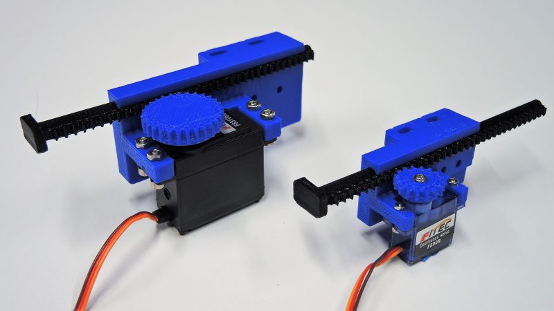
Unless someone has done the work for you, of course. That’s what [Ali] from PotentPrintables did with these 3D-printed linear actuators. It’s a simple rack-and-pinion design that’s suitable for light loads and comes in two sizes, supporting both the 9-g micro servos and the larger, more powerful version. Each design has a pinion that has to be glued to a servo horn, and a selection of rack lengths to suit your needs. The printed parts are nothing fancy, but seem to have material in the right places to bear the loads these actuators will encounter. [Ali] has included parts lists and build instructions in with the STL files, as well as sample Arduino code to get you started. The video below shows the actuators in action.
We’re heartened to learn that [Ali] was at least partly inspired to undertake this design by a previous Hackaday post. And we’re glad he decided to share his version; it might save us a few steps on our next build.
[via r/Arduino]


Didn’t think you needed a motorshield for a servo
You don’t, provide sufficient power to the servo and control the input with analogWrite and it works. [Ali] probably had another reason for using a motorshield but for just controlling a servo it’s not necessary.
You don’t- it just has the servo plug already integrated and is nice for controlling a bunch of different motor types (DC, servo, stepper).
The servo shield was a dark-green cloud over an otherwise fun video.
Perhaps custom gears could be made for the larger servos, to use screws for holding the circular bell-crank on.
With photo-interrupters or hall-effect sensors, you can know your limits.
Depends on the PWM output of the PLC, Arduino for example does not work with many Servo motors because of that, instead a 555-timer would be used or some other buffer.
nothing fancy, it does what it needs to and at a very very low cost, cool concept.
Fascinating, nice to see, thanks :-)
Provokes me to open up a few different production RC servos to determine if it possible crafting a suitable notched rod carefully placed in the appropriate location inside the product’s ‘unused’ space ?
It probably won’t be ideal at first in a few ways though might offer other options for consideration once some J itisl momentum set ie to further provoke others to augment their own way and if not a notched rod then a nylon/HDPE toothed belt as lowest cost path of exploration…
*some initial momentum
2 min perished edit option helpful eg reduce noise etc
Awesome, your timing is perfect, i was just making a Diy bed prob using a optical sensors from old printers and needed simple way of lowering the metal rod that acts as the probe/contact trigger. Thanks Hackaday.
Glad you like these and thanks for the article!
Why not just make two notches in the 3D-printed gear to insert a “two-sided horn” (sorry I don’t know the servo-motors lingo) and screw holes to keep it in place? That way you bypass the need for the epoxy.
I see there’s already a screw at the top of the shaft to keep it in place so only one notch to insert the same cut horn. Keep the horn as long as the diameter of the gear, that’s your way of transferring motion to the 3D-printed gear.
That certainly can work- I was trying to keep the diameter of the pinion gear down as much as possible, due to space constraints on the project this design was from. I just carried that constraint through to these generic designs.
Some comments from the video…
You can print servo splines on an FDM printer, I did with a Monoprice Select Mini. The resolution isn’t quite high enough to match the spline perfectly, but you can get enough bits of teeth to work. And it takes some experimentation to get the sizes right,
You do not need a motor shield, you just have to connect the wires to ground, 5V, and PWM. Oh, and the 5V regulator on the arduino may not (will probably not) supply enough current for a servo.
It would be a lot more useful to add end-stop switches or wire up a potentiometer to the servo control board (and gear it to the motor and/or the rack). In the case of using a pot, starting with a standard servo may make more sense than a CR servo.
Sounds like you are ready to do a remix with a fully printed pinion gear!
I had a home switch on the version I used in my Mouse Droid build, but wanted to keep this as simple as possible. I included the .step files with the STL files if you want to add mounting for a switch back in. I can even give you the vendor and part number I used for the switch.
I went and looked up your Mouse Droid, very cool! I also build robotics projects and have on several occasions thought about designing a 3d printed linear servo, but the complexity has always made me think of a simpler way. (Like I would have probably used a spring to open the door). But your linear servo is really cool! So, I might just use it as a starting point and add some end switched. The trick will be to do it without making the whole thing too bulky.
interesting. It means I don’t have to keep ripping the motors and sleds out of old CD drives.
FYI: ”Linear servos” are available from aliexpress at around $6. They are tiny. They are a good option if you need tighter gear alignment and direct position feedback at the output arm.