Finding just the right off-the-shelf part to complete a project is a satisfying experience – buy it, bolt it on, get on with business. Things don’t always work out so easily, though, which often requires the even more satisfying experience of modifying an existing part to do the job. Modifying a stepper motor by drilling a hole down its shaft probably qualifies for the satisfying mod of the year award.
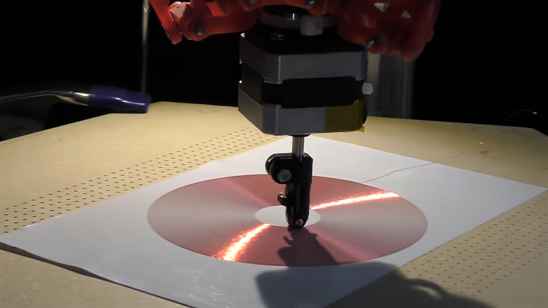
That’s what [Russ] did to make needed improvements to his CNC flat-coil winder, which uses a modified delta-style 3D-printer to roll fine magnet wire out onto adhesive paper to form beautiful coils of various sizes and shapes. [Russ] has been tweaking his design since we featured it and coming up with better and better coils. While experimenting, the passive roller at the business end proved to be a liability. The problem was that the contact point lagged behind the center axis of the delta, leading to problems with the G-code. [Russ] figured that a new tool with the contact point at the dead center would help. The downside would be having to actively swivel the tool in concert with the X- and Y-axis movements. The video below shows his mods, which include disassembling the NEMA-17 stepper and drilling out the shaft to pass the coil wire. [Russ] also spent some time reversing the rotor in the frame and provided a small preload spring to keep the coil roller in contact with the paper.
A real-time coil winding session starts at the 21:18 mark, and we’ve got to admit it’s oddly soothing to watch. We’re not sure exactly what [Russ] intends to do with these coils, and by his own admission, neither is he. But it’s still pretty cool to see, and the stepper motor mods are a neat trick to keep in mind.
Thanks to [Baldpower] for staying on top of this one.


Brilliant!
The paper is slightly sticky, so that the wire adheres – right?
Now if there were a way to accurately cut the wire as it was being laid, could you use bare copper wire and make PCBs at home using this technique?
Sure, but if you’ve retooled a 3D printer like that for laying copper… you might as well just add a spindle motor and CNC copper clad PCBs the right way. No finishing (unless you want a conformal coating) or anything. Mill, drill, cut to size.
Induction cocker?
But just a question, does it twist the wire between the spool and the toolend?
judging from the comments on the vidoe more like “over-unity” nonsense, but maybe not
It looks like it doesn’t. At one point in the video, you can see the spool, and it is not rotating.
Probably not important for this kind of low-torque application, but I’ve seen warnings that removing the rotor from a stepper motor can easily reduce its magnetism permanently.
All I can find is that this may be true for old Alnico magnets over a long period of time. https://forum.allaboutcircuits.com/threads/loss-of-magnetism-in-permanent-magnets.58689/
Well that seems far fetched, but this might be more relevant https://www.cnczone.com/forums/stepper-motors-drives/129500-machinist.html
More more relevant, testing from Mariss of Geckodrive fame: https://www.cnczone.com/forums/general-cnc-machine-related-electronics/903-disassembly-stepper-motors-post6803.html#post6803
Spoiler: disassembly reduced the strength to 62%.
I think that invert the rotor is worse than this.
That’s just nonsense that has grown into maker mythology. I think the actual reason for reduced torque after reassembling stepper motors is not getting it aligned properly, like maybe due to positioning one of the end bells 90 degrees from its original orientation.
Correct, misalignment is the reason for it being weaker after reassembly. However, it only takes a slight misalignment. This depends on the construction of the stepper motor. Some smaller steppers have two coils, one in the top shell, one in the bottom. If they are misaligned by a small amount, think about a 1.8 deg/step motor.
For the stepper motor in this video, I don’t see anything that can be misaligned.
Or maybe, getting contamination (i.e. metal dust or filings) into it that makes a magnetic short circuit between the poles.
In any case, if not having the magnets in a circuit for a short time damages the magnets, how do the magnets survive the assembly process in the first place?
https://en.m.wikipedia.org/wiki/Magnet_keeper
How much motor torque was lost by disassembling the motor?
This reminds me of something Bas did about 4 years back.
https://basdebruijn.com/2014/05/additive-wire-laying/
He could have feed the wire sideways in the attachment below the motor instead of directly above the motor. The wire just need to pass in the center of the rotational axis via a short hollow tube in there. It would require mounting the wire spool to the attachment instead of above the stepper.
This would have meant swinging the spool of wire around as well as having it be part of the moving mass, and he was already concerned about the amount of moving mass with the stepper motor. But I guess it would work to mount a just a bobbin of wire directly on his roller mechanism. Which also, by the way, would remove the potential problem of wire twist becoming an issue with a coil consisting of many turns. This didn’t appear to be a problem in the video, but that was with 40 AWG wire – any bigger, and it could be a problem.
I’ve re placed a leadscrew interested into a motor. It was basically just glued on.
I really like this guy’s machine. Very intriguing. I wonder if he knows that hollow shaft stepper motors are commercially available?
Could this be useful for inductive power applications? I think a wireless mouse that used this (would have to stick on a transmitting mousemat instead of a plain desk) would be much preferable to batteries.
Alternatively, one of the stages of a Tesla coil? You could spray some adhesive between layers and “print” another coil directly on top of the first…
Such micemat and mouse combo were common once.
It died out thanks to being stuck using the bundled and often shitty and thick mat.
They are definitiely still a thing.
https://www.logitechg.com/en-nz/products/gaming-mouse-pads/powerplay-wireless-charging.html
The primary coil for Tesla uses very thick wires as it has to handle a lot of power. It isn’t that hard to wind as it has very few turns.
The beginning and end point of the secondary coil have very high voltages difference and your “printing” it on directly on primary coil is asking for trouble. You also want lower capacitance and high inductance with low coupling which that configuration isn’t going to happen. You’ll need to have a very thick insulation between the primary and secondary layers.
This ain’t the application you are looking for.
hmm. i wonder if he ever saw a record disc. then a setup with a turntable and a linear lead screw could outperform this setup if sticking to circles. of course squares are out with this…
Previous versions of this machine were used to make coils with different shapes, and he mentioned that arbitrary shapes were a design goal. I think the circular coil here is just the simplest test case. Even if circular was all he needed, it might be easier to just use the delta he has rather than build a new rig that can only do one thing. But it would be cool to see.
Yes, but a delta needs much more math, as all coordinates are dependent from each other. I don’t understand the advantage of the delta configuration against an x/y/z anyway.
Low carriage mass, no inertia from a moving bed, much smaller footprint to bed size ratio than most cartesians.
Just as with the stepper motor, it was what he had.
If the turntable was powered by a stepper then all that’s keeping you from making square coils (or any other shape) is a bit of math :)
I think you guys may all be missing the point: he used what he had available, which happened to be a delta printer. As such, this was a simpler solution than putting together a complete coil printer from raw materials. He also didn’t have to deal with the more complicated math needed for delta printers, because I’m pretty sure he already had something on hand that converted from Cartesian coordinates to delta heights.
Yes, please show us the steps in soft ware,
Also can you think about some software diagnostics
To let the human that there is a mishap with the machine?
Also can you remote the vac motor to the other room and just use a tube for the vacumme air? Less noise that way, thanks!
Can you use this and substitute the copper wire with some form of carbon fiber to make up a auto layup machine for carbon fiber parts?? Please include an injector of the glue so the carbon fiber is formed in to an epoxy base . Then we can get on with our carbon fiber layups for our electric bikes, thanks.
An alternative would a fixed wire feed point, above a gantry that moves a rotating table which is mounted on a stepper. Move the sticky paper table leftwards on the gantry traverse mechanism, and slowly rotate the sticky paper to effect the coil.
That seems like a good idea. It removes the problem of wire twist, which may become an issue with larger wire gauges.
Metal detector coil?
23:13 – needs to be in one of those “most satisfying videos” compilations.
So the rotor spins inside the motor.
And it was removed, fixed to a lathe stock that spins, and drilled.
I wonder – could one drill a hole in a stepper motor shaft using its own coils to spin it?
I’m no machinist but I’d guess that the torque is too low for that.
But at least it should be possible without disassembling the motor. Grab the free shaft end with the lathe chuck and drill. For me in this case it seems even unimportant, how much the stator of the motor turns in the bearings or not.
What is this used for?
Flat coils
This would be a nice tool to make the secondary coils for flat teslacoils: https://hackaday.com/2017/10/30/pcb-tesla-coil-is-perfect-desk-toy/#more-279325. You can make fast iterations and use different wire sizes to optimize the coils.
How about planar magnetic speakers? It shouldn’t be that difficult to have this lay out the wires in different shapes suited to this.
I’m picturing a much larger Cartesian machine.
I have an 18 inch wide laminator that uses two rolls of thin (1 or 1.5mil) laminate. I wonder if I could lay out a sheet, adhesive side up, then have a tiny hot air nozzle just ahead of the wire. Then laminate the second layer on top.
It seems like he’s doing a lot of work to effectively avoid creating a drag-knife looking affair. Not only do drag-knives cut on a lag against where the spindle centre is but they don’t even use a stepper motor to ensure orientation. Just by being a bit careful with the g-code generation, one can negate the spindle offset issues and still achieve fairly tight corners (think of how sharp squares are on vinyl signs).
Anyone know why he went away from a drag-knife style and onto something elaborate?
It says why in the article.
“While experimenting, the passive roller at the business end proved to be a liability. The problem was that the contact point lagged behind the center axis of the delta, leading to problems with the G-code. [Russ] figured that a new tool with the contact point at the dead center would help. The downside would be having to actively swivel the tool in concert with the X- and Y-axis movements.”
This seems like a better, if more complex, solution than offset compensation.
But that’s just it – their problem was that they couldn’t write g-code (offset compensation – already solved in every drag-knife g-code generator) so to fix it they’ve written a tool that generates g-code. How was the drag knife version a liability?
To me it seems like they just plain ignored something that has already been solved and instead generated a new problem that they needed to code for (generator g-code for their stepper).
Having it motor driven makes it more controllable.
I wonder if he could make difference coils for wearables, and do it cheaper than flexible pcb designs. You can make difference coils that can detect electrical signals from the heart, or from gastric peristaltic activity (as the muscles tense and untense). If he can do automated wire cutting and multiple coils on the same sheet (an array of coils) I actually can see a sheet of sensors being made using multiple sheets combined together.
As an alternative, could this be used for making heating coils that can be embedded in clothing?
Hi dan
I am a 3rd year student of aerospace manufacturing and looking for a project to manufacture , and your stifling engine looks like what interested me , I want to manufacture a 16 cylinder gas powered stifling engine and I want your help from where to start from , and also how long will it take me to make it .
Hoping a soon reply from you
Thank you
Charmish
I think you meant “Stirling”.
Heh, They charge twice as much for a through-hole shaft. Spin your own!
Drilling through the motor shaft was an unnecessary complication, as you can easily buy hollow-shaft stepper motors. For example: https://www.digikey.com/product-detail/en/adafruit-industries-llc/324/1528-1062-ND/5022791&
It seems like he’s doing a lot of work to effectively avoid creating a drag-knife looking affair.
I also think that invert the rotor is worse than this.