Soyuz Failure Leaves Questions Unanswered

The Russian space program experienced its first serious incident on a manned mission in 35 years when Soyuz MS-10 failed during ascent on October 11th, 2018. The abort system worked as designed, and crew members Aleksey Ovchinin and Nick Hague landed safely approximately 430 km from the launch site in Baikonur. Beyond being put through unusually high G forces, the two men suffered no injuries and will have their mission recycled for a future flight.

From an abort standpoint, the event went as well as could possibly be expected. The fact that the crew walked away unharmed is a testament to the emergency systems on the rocket and spacecraft, and serve as a reminder of why these functions are designed into manned rockets even if they are rarely (if ever) used. The success is especially impressive considering the Soyuz’s launch abort tower, the solid fuel rocket designed to pull the spacecraft away from the failing booster rocket, had already been jettisoned before the event occurred. The spacecraft was instead pulled to safety by the secondary abort thrusters, which were added to the vehicle’s design in 1975 as a contingency and until now had never been used in a real-life scenario.

What Went Wrong?

But while the safe return of the crew was naturally the first priority for all agencies involved, the questions soon turned to the Soyuz itself. What caused the loss of the rocket? Is it a defect which could be present in the other Soyuz rockets currently under construction? Perhaps most importantly, when could the Soyuz fly again? As it’s currently the only way to put humans into space, the International Space Station is completely dependent on regular Soyuz flights, and a delay in the program could endanger the orbiting outpost.

Now, with the initial findings of the Russian incident investigation being made public, we’re starting to get answers on some of those questions. The official report so far agrees with the conclusions many “Armchair Astronauts” made watching the live stream of the launch, and the evidence suggests that the core issue is the same which doomed previous Russian vehicles.

Continue reading “Soyuz Failure Leaves Questions Unanswered”

The Negative Rail Explained

With the high availability of modular components and incredible wealth of information and tutorials online, it’s now easier than ever for hackers and makers to assemble complex electronic projects without getting bogged down with the theory behind it all. But the downside is that the modern electronic hobbyist often doesn’t have as deep an understanding of the low-level concepts that they would have if they had to build everything from scratch. This can be a problem when they try diagnosing and repairing faults, or when they start to branch out into reverse engineering.

Which makes “Building Blocks” by [David Christensen] a very compelling series. Every week he will be demonstrating a new circuit on his blog, complete with a plain English explanation of how and why it’s used. In this first installment of the series, he’s tackling a concept most of us have seen when poking around in more complex electronic devices, but maybe never really gave much thought to: the negative rail.

What exactly is the negative rail, anyway? It’s pretty easy to understand the positive rail in a circuit and its relation to ground; even multiple positive rails, such as in devices which use both 5 V and 3.3 V, are simple enough to wrap your head around. Unfortunately when something drops below that logical 0V reference, it isn’t quite as intuitive. But as [David] explains, the negative rail in a circuit is critical for dealing with bipolar signals, such as audio, which ride above and below the 0 V center point.

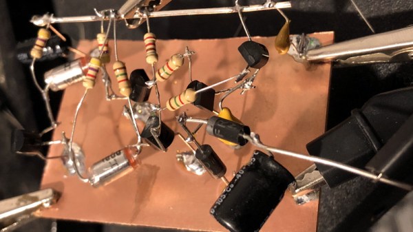
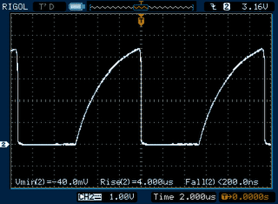
[David] goes over a few methods used to create the negative rail, from the classic center-tap transformer to using a buck-boost converter. But not content with just describing how these circuits work, he walks the reader through the creation of a charge pump circuit that you can drop into your next project if you find yourself in need of the elusive voltage. After explaining and diagramming it, he builds the circuit on a scrap piece of copper clad board and puts it through some benchmarks to prove it matches the theory he laid out.

If you’re in the mood for more negative talk, check out the battle our very own [Steven Dufresne] had with voltages of varying polarity when building his BB-8 robot.

All The Goodies You Need For Your RTL-SDR

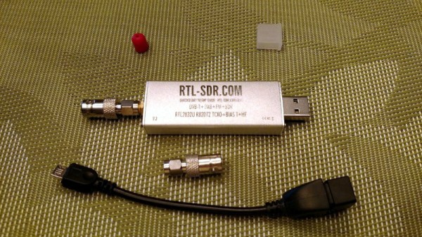
When the RTL2832-based USB digital TV sticks were revealed to have hidden capabilities that made the  an exceptionally cheap software-defined radio receiver, it was nothing short of a game-changing moment for the home radio experimenter. The RTL might not be the best radio available, but remains a pretty good deal for only $10 from your favourite online supplier.

Having bought your RTL SDR, you will soon find yourself needing a few accessories. A decent antenna perhaps, an HF upconverter, and maybe an attenuator. To help you, [IgrikXD] has come up with a repository containing open-source implementations of all those projects and more. There’s an HF upconverter handily in both SMD and through-hole versions, as well as a wideband active antenna. A resonant antenna for a single band will always out-perfom a wideband device if your interest lies on only one frequency, but when your receiver has such a wide range as that of the RTL it’s irresistible to look further afield so the wideband antenna is a useful choice.

The RTL SDR is a device that just keeps on giving, and has featured innumerable times here since since its first appearance a few years ago. Whether you are into passive radar or using it to decode data from RF-equipped devices it’s the unit of choice, though we rather like it as a piece of inexpensive test equipment.

Via Hacker News.

Header image: Joeceads [CC BY-SA 4.0].