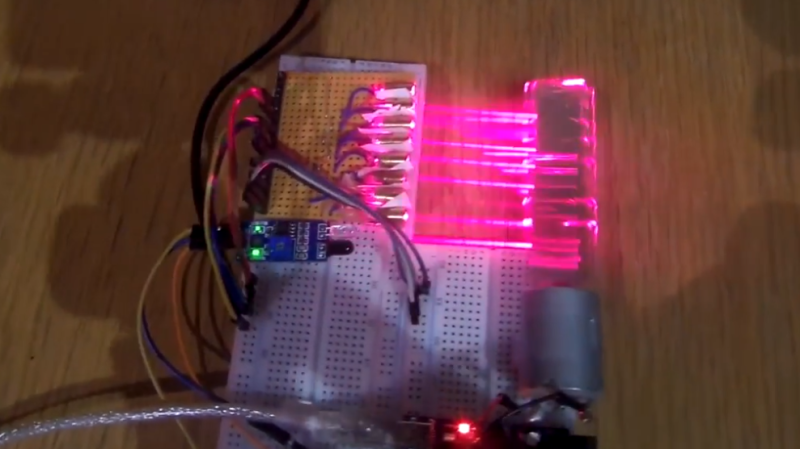
[XTronical]’s idea for a laser-based persistence of vision gadget failed, but the basic idea seemed sound. A row of inexpensive red lasers shine into a spinning mirror and are reflected onto a distant surface, making 8 scan lines. A reflective object sensor detects mirror position, and by rapidly turning individual lasers on and off, a pattern can be drawn out.
That was the idea, anyway. A quick prototype consisting of some small and economical red laser diodes and a double-sided mirror hot glued to the shaft of a small DC motor formed the guts of the unit. [XTronical] worried that the spinning mirror might be unstable or unreliable, but that part performed just fine. The problems, he found, were mainly with the lasers.
[XTronical] had hoped to turn the lasers on and off directly via the digital I/O pins of an Arduino, but here’s where a lot of little issues sank the project. First of all, hot glue was handy for mounting but the lasers were cumbersome to align by hand, and the hot glue made it troublesome to effect repairs when units failed. In addition, the beams had inconsistent brightness and spot sizes, which made for poor visuals. [XTronical]’s approach of controlling the lasers by applying and cutting power may also have been a source of trouble. It’s possible that these lasers cannot turn on and off fast enough, but it’s hard to say without measuring.
Sensible ideas can be rendered unworkable by an accumulation of small problems, and that seems to have been the case here. A video overview is embedded below; is this approach doomed, or can it be made workable?
Persistence of vision gadgets come in all shapes and sizes, even jump rope has been pressed into service as a PoV display, and it’s a pity this attempt at a display didn’t work out.


It would have been easier to pull the laser head out of an HP LaserJet printer.
The laser would not useful, being infrared and thus invisible. The rotating polygon mirror+motor, driver, and other optics, however, would help enormously.
Didn’t some (ancient) laser printers use HeNe tube lasers?
Probably, before 1980 or so. The one we bought in ’87 was big and heavy enough to, but I’m pretty sure it (and the previous 1985 LaserWriter) used a diode.
Aren’t they UV (being used to locally discharge the drum to form the image)? Couldn’t you easily replace the UV laser diode with one of a different wavelength?
Also, this arrangement is used in every laser printer and photocopier I’ve ever disassembled (dozens, from most of the major companies), not just HP LaserJets.
UV? You tell us: measure the wavelength of one of those dozens of lasers you have got. Or, easier, just read that friendly yellow label that states the power output and wavelength. Please report back.
And, sure, you could replace the laser printer laser with a visible one, and get a single line output (at a few hundred lines per second). Follow that with an orthogonal tilting mirror and you can build up a raster image.
No, they are IR. Around 780nm IIRC.
If they were UV then UV laser diodes wouldn’t cost hundreds to thousands of dollars for a few mW.
Attaching the mirror to something at the other end would solve the wobble.
A second motor wired in reverse!
> It’s possible that these lasers cannot turn on and off fast enough, but it’s hard to say without measuring.
It takes time to turn on a Laser so that’s why they don’t completely turn it off if you need to switch at Gbps speed.s
This application would only need switching in microseconds range. Arduino DigitalWrite() would be a likely suspect for timing issues. The code probably be slower than what the Laser is capable of.
Also whatever used as a light sensing feedback needs to be fast enough.
It’s not so much “time to turn on a Laser”, as it is the other electronics in the way.
Even cheap modules like the ones here have on-board current regulation. Better ones have on-board optical power feedback too, to regulate output. In either case, that control loop isn’t *that* quick, and you probably can’t modulate these at MHz rates by switching the supply on and off.
Better would be to get inside that module and modulate *its* driver directly.
If you have an unregulated module (i.e., a naked diode), but a good wide band constant-current driver of your own, then it may be better to set the idle current to a bit below the lasing current (maybe 50% of operating current), and modulate 50 to 100% rather than hard off/on.
Back before Wifi, some hackers figured out how to send Ethernet over laser pointers. I recall that the ones that worked were the really cheap ones that just have a resistor to limit the current. The fancy ones were worthless for that use…
Thinking of RONJA ?
I’ve sent audio over lasers, and yes, the ones that just have a resistor work fine. If you replace the constant current supply with one that uses an enable pin, those work for audio frequencies but not much higher.
Red only. Green uses frequency doubling, and that seems to lower the bandwidth too much to be usable.
“Green uses frequency doubling, and that seems to lower the bandwidth too much to be usable.”
It’s not the doubling process: that part has a very high bandwidth: I’ve measured well over 50 MHz, limited by my detector, and it is certainly much, much higher. Likewise the Nd:YAG pump laser.
So, no, the slow response of the green laser is due to the control loop. Recall that a green laser actually has three quite non-linear stages: Input DC current pumps a 808 nm (or so) diode laser; which pumps a 1064 nm Nd:YAG laser; which then goes through the doubling crystal to 532 nm. Because each of those stages is (at least) a square-law, a tiny change in the pump diode current yields a large change in the output intensity. It needs to be tightly controlled because even a small input current excursion will ablate mirrors and filters in the later stages. A slow loop is easier to engineer, and cheaper.
Tuning it to yield higher output will also exceed the ‘allowed’ output, but the optics are also generally engineered only to be good enough for the desired output power, so turning it up to get more output works only for a little while. Sadly, the results of ablating a mirror at elevated power are unspectacular.
The LASER mounting here I think made it rather tricky. Why not holes in a bit of soft wood? You can Macgyver up a way to get the holes parallel even without a drill press. As for the speed, These lases must be able to switch at pretty high speeds. I would suspect the C in the Arduino. Check the driving signal with a scope. It will help to see the code.
“…get the holes parallel” is nowhere near enough. The beam does not generally come out aligned with the case: The collection of 10 or so similar modules I have here point only vaguely in the same direction: some a few degrees out, dozens of times their beam width. You need individual 2-axis pointing control for each laser module, or one axis physically adjustable (laterally or in rotation, doesn’t matter), and adjust the other dimension in the timing.
I have a handful that look the same but are pretty old and probably different. They are OK for a test and I see your point. Something more clever with a screws or wedges for each one. Maybe a flexible hinge and one wedge for each. In-out for one axis and slide left-right for the other with the hinge as the pivot. I think it could be made from a single piece of wood with straight cuts to keep it quick and simple.
Well, if you want it *simple*: no hinge or wedges are required. Just make the module rotatable in the hole. At some point in its rotation it will be pointing normal to the rotation axis. Setscrew or glue it there. Repeat for all the other lasers. They will all end up parallel in one axis, but varying in the other (time, or rotation) axis. Adjust that in the output bit timing.
It’s an annoying but one-time calibration. No fiddling with 16 mechanical adjustments required.
If you are truly picky, you’ll need to make that calibration (very) slightly dependent on the projection distance, but it very likely won’t be noticeable.
Good idea, but are you thinking of spinning the diodes? Or is that normal to the mirror, in which case I can’t picture it quite right.
Yes, “spinning the diodes”, as in “rotate on their cylinder axis”.
No picture, use your imagination:
Picture the axis the mirror rotates on.
Picture a stack of parallel planes, with that axis normal to (and passing through) them.
On each plane, place a laser, pointing toward that axis.
At this point, you’d want to individually adjust each laser in pitch and yaw to aim their beam at the point where their plane intersects the mirror axis.
Instead, simply rotate (roll axis) the laser so its beam lies in its plane. It might be a bit wall-eyed in yaw, but it’s still heading toward the mirror, and this roll adjustment (on each laser) make sure they all form parallal planes of light when the mirror rotates.
You adjust their yaw electronically, in software, by adjusting the timing so they all line up “vertically”
Better?
Actually, I think hot glue is pretty close to an ideal mounting here. Just change the process a bit.
Turn the lasers on while mounting and shine the thing at the wall on the other side of the room as you glue them down. With just a bit of planning you could draw up a paper target with expected aim point for each of the lasers. At that point it’s only a strait line with each one having the same separation distance. (think ruler)
Mounting parallel in wood was my first idea, but then quickly discovered that these cheap lasers do not fire out in a repeatable way between devices. You can lay them on a flat surface and they are all over the place after just a meter or so. I did exactly as DKE suggested and pointed at my wall whilst I aligned. But hot glue stayed fluid for to long whilst trying to hold steady. I needed some sort of jig to hold in place or better some sort of mount to align laser easily post fitting
The question is, do they want to use the remaining eye to attempt the project again.
For these just keep your eyes focused close – not at infinity – so you get blur instead of a finely focused spot on your retina.
I’m not sure manual focus is something most humans have as a feature.
If I remember I used a photo diode /transistor for the light sensing feedback which was responsive enough to get rhe mirror to spin at a accurate speed.
This project is rightly named fail of the week, it did not go well…
Welcome to the FotW club! Your flowers and fruit basket should be arriving in a day or two. As a veteran here I want to point out that the only people who never fail are people who never try anything new. You’re in good company, chin up, keep going!
Cheers, least it made hackaday anyway!!!
There’s a lot to learn from failure in a positive way, and I’m delighted that you took the opportunity to share what happened and what didn’t turn out as expected. Thank you!
I also have use those same (or similar) diodes and it was a bit surprising to discover that the beams, as you said, are not necessarily lined up with the laser’s physical enclosure. Sometimes not even close.
Maybe candlewax would work better than hot glue. It would be easier to re-melt and adjust.
Sounds a good idea. Thanks.
Pwm driving of the laser just below or at visibility threshold. It’s what’s recommended for the diode 5watt laser I picked up.
Yep. Without a real-time optical power monitor feedback on the diode that’s the only reasonable way to adjust output power — the laser threshold varies diode-to-diode, with temperature, with age, and heck, probably cosmic rays and phase of the moon too.
I did exactly this myself: check it out here:
https://www.instructables.com/id/Laser-Sign/
Well im glad someone tried to do it with these exact laser diodes i have. And FAILED.
A couple years back i wanted to do the same but attach the whole thing to a ceiling fan, instead of spinning mirror. fire up the fan and bam laser POV. could write things all around the wall of the room.
Looks like i would have failed with these. guess i now know to check switching speed before i attempt this project. thanks for the fail info.