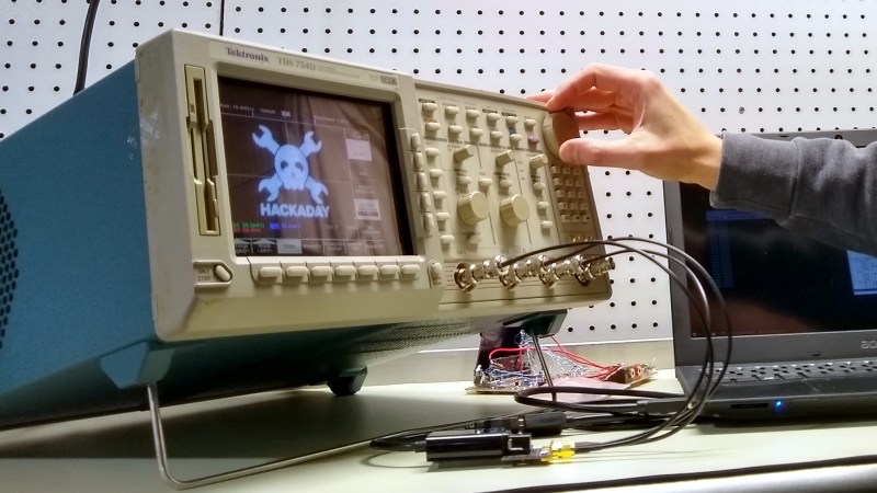
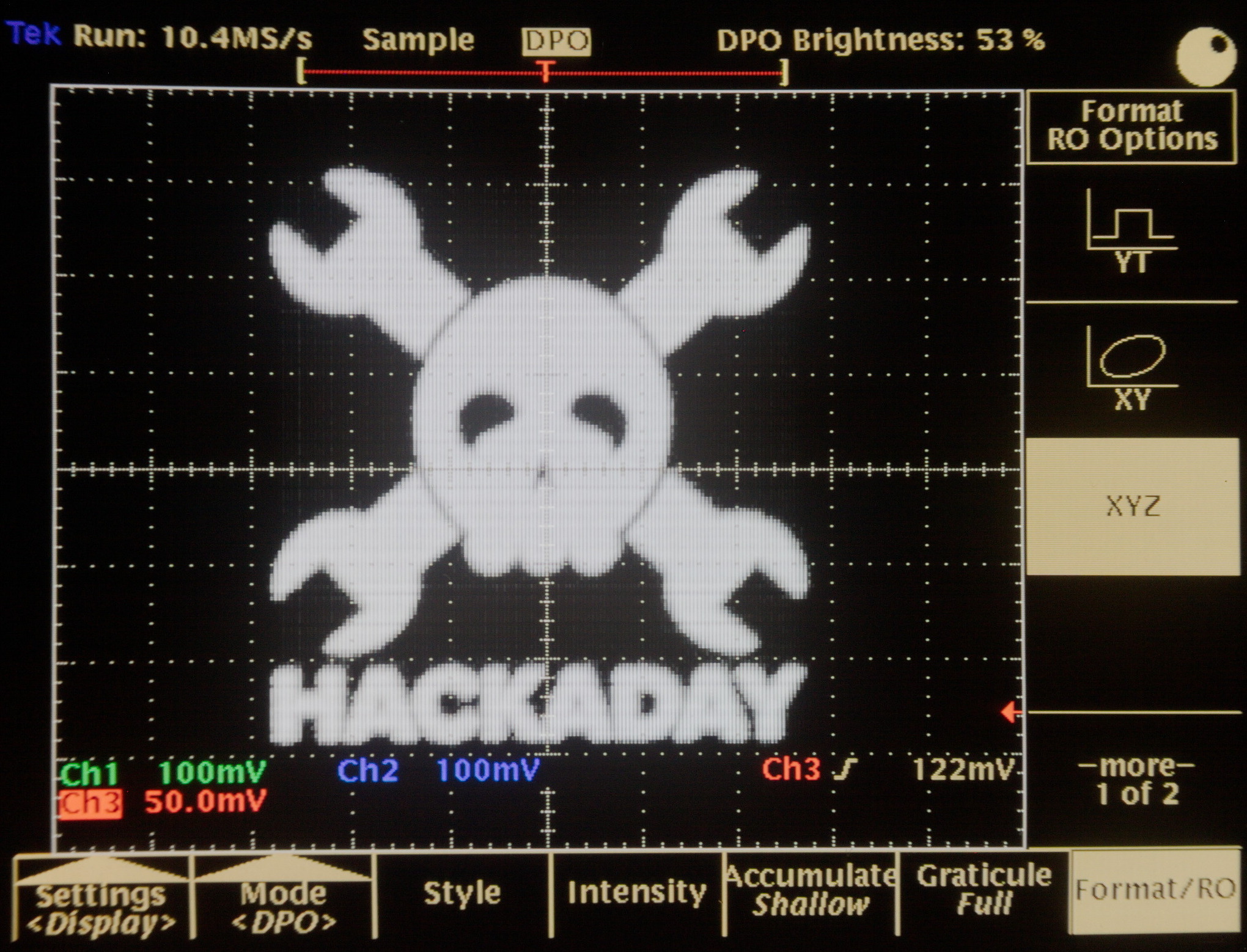
I recently came across the most peculiar way to make a color CRT monitor. More than a few oscilloscopes have found their way on to my bench over the years, but I was particularly struck with a find from eBay. A quick look at the display reveals something a little alien. The sharpness is fantastic: each pixel is a perfect, uniform-colored little dot, a feat unequaled even by today’s best LCDs. The designers seem to have chosen a somewhat odd set of pastels for the UI though, and if you move your head just right, you can catch flashes of pure red, green, and blue. It turns out, this Tektronix TDS-754D sports a very peculiar display technology called NuColor — an evolutionary dead-end that was once touted as a superior alternative to traditional color CRTs.
Join me for a look inside to figure out what’s different from those old, heavy TVs that have gone the way of the dodo.
High-End Tools, High-End Hardware
Electrical engineers depend on their oscilloscopes to see what’s happening inside a circuit. If you’ve ever tried debugging without one, you know what a difficult and frustrating experience it can be. Consequently, users expect these devices to provide accurate representations of electrical waveforms: to be an extension of their eyes. If asked to name the most important part of a scope, what would you say? The attenuator or amplifier? The timebase? The ADCs? The probes? In today’s screens-everywhere world, probably not many would say the display. But, for a generation of engineers brought up on analog scopes, the display was of paramount importance. Hence, the designers wanted the display to be as sharp as possible: any fuzziness should be due to the signal (like my bandwidth-limited wrencher), not the instrument.
Analog oscilloscopes were very sharp, and they were monochrome. This was in keeping with their original function: to plot voltage (y) vs time (t), or in some cases, voltage (y) vs voltage (x). Color doesn’t add much to such a display, although many scopes also had a z-input to modulate the trace intensity. And while dual-beam scopes existed (for displaying separate channels simultaneously), keeping three beams synchronized as they swept across the display to create a real-time color trace would have added a great deal of complexity and cost for little return.
When digital storage scopes arrived, and the display evolved from a simple graph to a full user interface, color took on new importance. Different colors could be used to disambiguate traces, visually link them to automated measurements, and distinguish text and UI elements. Later, with the advent of digital phosphor oscilloscopes (DPOs), which did a fancy digital simulation of a real-time analog scope, color could be used to reveal subtle features of the waveforms themselves. So, it made sense to add color displays.
But, if you were building high-end oscilloscopes in the early 1990s, your choices for color displays were limited: color CRTs and LCDs, and each presented problems in oscilloscope use.
Color CRT Issues
The traditional way to display color images on a CRT was to use three electron beams striking an array of primary color phosphor dots (or in some systems, stripes). Several technologies were developed over the years, but they all share a common mechanism: a perforated mask of some kind is interposed between the cluster of electron guns and the screen, producing pinhole images of the three beams, hopefully with each one hitting the intended phosphor dots. In reality, this didn’t always happen, so blurriness and impure colors were common display artifacts. The use of separate color dots also meant a loss of spatial resolution: the smallest possible pixel was a cluster of red, green, and blue points.
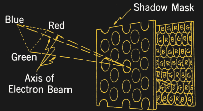
Focusing a single electron beam into a tight dot is not a problem; scanning electron microscopes can have beam widths less than a 1 nm, although admittedly, they scan over a much smaller area relative to their size. The true difficulty is in keeping three beams aligned with each other and with the phosphor mosaic. As a result, monochrome CRTs suffered fewer image quality issues.
Not only was color CRT display quality problematic, but the devices themselves were bulky, heavy, and sensitive to vibration and shock, which could knock them out of alignment. Although some oscilloscopes were made with traditional color CRTs, the technology was far from ideal.
Why Not LCD?

Some competing oscilloscopes at the time were the first to use LCD screens. But, color LCD screens from that era were a far cry from the excellent displays we enjoy today. They suffered from low contrast, poor color quality, and had abysmal viewing angles. These were the early twisted nematic (TN) displays, primitive compared to today’s version, as in-plane-switching (IPS) displays were still a few years off. Even today’s LCDs haven’t managed to fix one of the original problems: each display pixel is still composed of primary color sub-pixels. Although this can occasionally be used to advantage, for instance in sub-pixel anti-aliasing for rendering text, it can also impart a blurriness to individual pixels.
The Tektronix NuColor Display
Instead of using either of the these existing technologies, the engineers at Tektronix decided to leverage their extensive experience with monochrome CRTs to create a superior display. They started with a traditional monochrome CRT with a white phosphor, then added an ingenious system of switchable colored filters to create a field-sequential color display. In this system, instead of the primary color components being distributed in space, pointillist style, they are distributed in time, with successive frames showing red, green, and blue components of an image. To the eye, the result is the same: primary color components for each pixel get blended into a perception of different colors. The marketing department over at Tektronix dubbed the technology “NuColor.”
The biggest advantage to this system over color CRTs, and even modern LCDs, is immediately apparent: each pixel remains the same tiny, single dot as rendered by the monochrome CRT, but now appearing in your choice of color. Tektronix used a 180 Hz frame rate on these displays, so the full RGB display was refreshed every 60 Hz. The downside is an occasional glimpse of the individual color frames if you look away from the display quickly. This effect can also be captured with a high-speed camera.
Compared to color LCDs of the day, the other key advantages were brightness and contrast. The NuColor display had an enormous dynamic range driven by the monochrome CRT at its heart, putting the very poor contrast of contemporary LCDs to shame.
Polarized Filters for Each Color
To make this new display, Tektronix placed an electronically-controlled color shutter system in front of the CRT face. These color shutters were created using a type of liquid crystal technology, but instead of switching individual pixels, they switched the entire display at once, like today’s active 3D shutter glasses or auto-darkening welding helmets. In these LCD applications, light is passed through a neutral polarizing filter, creating polarized light. This light then traverses a liquid crystal cell which can rotate the polarization of light passing through, depending on applied voltage. Finally, the light exits through a front neutral polarizing filter. Depending on the amount of rotation that the liquid crystal cell applies, a varying amount of light is transmitted through the front polarizer.
In the NuColor display, instead of using neutral polarizing filters, Tektronix used color-selective polarizers. For instance, the first polarizer in their full-color system passed all three red, green, and blue colors of vertically polarized light, while allowing only green in the horizontal polarization. By combining three such polarizers, each with a different single-axis color, they were able to create a system that could selectively pass red, green, blue, or white light. Like DLP projectors which use a red/green/blue/white color wheel to produce brighter images than red/green/blue alone, these displays could have offered an expanded dynamic range, although this technique appears not to have been used on oscilloscopes.
Tektronix was granted at least 10 US patents on this technology. These ranged from a system that could display only red and green primaries (US Pat. 4,582,396), to one that could display three de-saturated primaries resulting in an all-pastel colored output (US Pat.4,674,841), to a full-color display with an expanded color gamut (US Pat. 4,635,051). In the patents and subsequent media coverage from the early 1990s, they touted the advantages of the new display technology in better resolution, lower power consumption, and smaller size and weight. They also estimated it would add only 2.5% to the cost of an oscilloscope, as opposed to 12.5% for a traditional color CRT.
Steady March of Display Technology
Of course, today’s devices don’t use field-sequential color CRTs. The technology behind the NuColor display just couldn’t compete with the size and weight advantages of LCDs. Once LCD quality evolved far enough, these displays came to dominate the digital oscilloscope market just as they did nearly every other screen. Although, with OLEDs on target to outpace LCDs in smartphones this year, that may be changing.
Obviously, the NuColor displays are not being produced any longer, so some enterprising types have started providing LCD replacements for the aging CRTs in these scopes. Luckily, these scopes also sport an analog VGA output port for an external monitor.
By the way, should you happen to find yourself in possession of a 500MHz TDS-754D like this one, note that it’s field-upgradeable to a 1 GHz TDS-784D by changing a few resistors and removing a few capacitors. If you dig through the thread on the eevblog, you can figure out how. It works, although it’s nowhere near as easy as software-only upgrades like we covered for the Rigol DS1022C, Rigol DS1052E, Rigol DS1054Z, and Rigol MSO5000.
One last note. I used the osmo-fl2k code we featured back in April to render our favorite logo on the scope: originally an RF hack that turns certain cheap USB-to-VGA dongles into SDR transmitters, it also comes in pretty handy around the lab as a $5 3-channel arbitrary waveform generator.


God I love old CRTs. Did they ever make any TVs or monitors using this technology, or just oscilloscopes? Really impressive the kind of maturity they got out of those machines before they became obsolete.
I found an old CRT projector sitting by the dumpster the other day and couldn’t help myself. The kind with oil lenses that both cool and focus the individual overdriven RGB tubes. Just the triple flyback transformer alone is interesting, wonder what I should do with it? Other than acknowledge my problems as a tech hoarder.
In the very early days of TV, they had a system with a B/W CRT and a color wheel to do the field sequential color filtering.
The colour video from the Apollo missions was accomplished using a camera with a B/W sensor and a colour wheel, too!
In the 1980s, I worked on a presentation graphics program (for IBM PC and MS-DOS) that could drive a Polaroid Palette film recorder. It had a B&W CRT in a box with a filter wheel and interchangeable camera bodies (some 35mm, some Polaroid peel-apart type).
https://en.wikipedia.org/wiki/Polaroid_Palette
This is also how most professional film recorders for the motion picture industry worked.
Though less often used in the modern age of direct digital distribution, back in the days of film projection you used one of these devices to make a film print of all your spiffy digital VFX work. The output had to match the rest of the movie, and camera film had gotten really good, so the output resolution was typically in the 4K range with 10 or so stops of dynamic range.
Though there were some devices that used scanned lasers, most of the high-res recorders I can think of had a modified motion picture camera pointing down at a very hi-res, hi-dynamic-range monitor. There was a filter wheel in front of the lens with RGB filters, and sometimes another wheel with ND filters, to improve the dynamic range by writing multiple exposure passes onto one frame of film.
Though it’s more rare these days to see film recorders, they’re still out there, making film prints for markets, especially in developing countries, where theaters still use film projectors.
Low end DLP projectors also use sequential color.
Yeah, a friend of mine does VJ work and he hacked one to get significantly more lumens out of it by simply removing the color wheel. If he needs a color he simply shines it through a gel, it’s mostly used for abstract graphics using sound feedback anyway so it doesn’t need full color.
I’m more interested if any other products used the specific NuColor tech. Having those variable polarized color filters working inside the vacuum tube itself is great. According to this it uses LCD tech, but I wonder if it would work better or worse using a Faraday cell to magnetically twist the polarity instead of blocking it with several filters, kind of like the rapatronic cameras they use to photograph atomic testing worked. Might get more brightness out of it, or at least be able to drive the electron gun at a lower voltage.
https://en.wikipedia.org/wiki/Rapatronic_camera
almost all but the highest end DLP projectors do, actually. It’s just that the low end ones are slower, so it’s more obvious.
In the new ones with LED projection this is hardly an issue anymore. No color wheel, just switch the R,G and B LEDs
Most of the single DLP, solid state light source projectors use a “Hybrid” light-source. Instead of a spinning dichroic filter like lamped projectors, they use a spinning phosphor wheel with a blue laser to generate red and green. Some others add in a red laser or red LED to enhance the color range. I can’t think of any projector over a few hundred lumens that is using only LEDs.
For example:
https://www.casioprojector.com/lampfree
https://www.christiedigital.com/SupportDocs/Anonymous/Christie-BoldColor-Technology-FAQ.pdf
Panasonic even still has the color wheel. It does still have the phosphor on a wheel, but this may just be for cooling purposes?
https://business.panasonic.co.uk/visual-system/solid-shine-laser-projection
It’s only in the last few years that we’ve seen true RGB laser light sourced projectors become widely available, and even then they are still largely in the very high end.
Can confirm, I have an XGIMI H1 and it uses three LED chips to shine light onto the DLP chip. The color reproduction and dark levels are amazing, but the overall brightness is limited by how hard they drive all three elements. Compared to a bulb type, it is clearly dimmer. The upside to that is reduced heat and working noise being almost nonexistent.
i want to say there is a video on youtube of a field sequential color tv that was branded montgomery ward
See this Technology Connections video for a JVC video monitor that uses it:
https://www.youtube.com/watch?v=z-q8ehzHeQQ
It’s also mentioned below by Simon (third top-level comment).
There was another technology used to give limited color: a dual layer phosphor where the two layers were different colors. Changing the electron beam intensity would vary the amount of energy that made it through to the second layer, giving a limited selection of colors. IIRC, this was also developed by Tektronix.
The company that made the Vectrex video game system built one layered phosphor prototype in an attempt to produce real color graphics instead of using the colored plastic overlays. They tested it at a couple of voltages, got different colors, then boosted the voltage more and burned a hole through the phosphors. That ended the color Vectrex project and soon after the company folded. The prototype still exists and even in crappy online photos you can see the dark spot in the center of the CRT.
https://en.wikipedia.org/wiki/Penetron
JVC made a professional video monitor using this system. Only 5″ but very bright and perfect color. I bought some for outdoor use for super high brightness. It ended up being more accurate than our much more expensive Sony reference monitors.
Any idea of the specific model?
JVC TM L450TU
Wish they had made a consumer TV using this, I’ve always thought CRTs gave a better picture.
CRTs could give a much better picture than a TV or VCR image. The real bottleneck is the PAL/NTSC CVBS signal. You couls see the difference already with te early home computers like a C64. When you were lucky and had an RGB connected monitor, the picture was much better than on a TV with RF or CVBS connection. That was the reason for Y/C connections for better video formats like SuperVHS.
“Consequently, users expect these devices to provide accurate representations of electrical waveforms”
Hah! Yah, Sure. I expect scopes in my price range to provide just as accurate representations of the waveforms I feed them as their 1990s “last inspected” stickers imply!
Patents should have expired by now so hackers should have a sequential field day.
What do you mean?
Patents on the display technology? How many here can make a CRT?
Reverse engineer the interface to the display in order to use it for other things? I’m not sure anything about that ever was off-limits. Also, outdated as it is 500MHz is nothing to sneeze at. If this scope is only a few resistors and capacitors from a 1GHz bandwidth then I think it is still too precious to destroy like that.
Duplicate the whole unit from scratch for sale? See that part about making CRTs. Then realize that this would be far too big a task to be worthwhile even if you had the display. Also that’s copyright not patent and the copyright probably will not expired until well after all our children are dead.
So what ARE you talking about?!?!
joke ?
Great article.
I have a list of hacks for the TDS-520 that I am going to start with for a Frankenscope as Tek Support noted one time I called in:
1. Clean and recap with longer lasting upgraded caps
2. FFT option enabled (GPIB adapter & custom Option 13 Module)
3. VGA Output (almost thinking I can add others like RCA… though not sure I need though interesting study)
4. 1M memory upgrade
5. Battery tap for Rechargeable or new NVRAM battery
6. USB Output
7. Battery Powered
8. Upgrade to color screen chipset
Eventually I’ll update the TDS-744a to a TDS-784a.
I need to learn more and practice my soldering skills on some other cheaper and older equipment in the mean time.
Would be nice to get into the firmware on these and see what the syntax and code looks like to explore other capabilities.
I have the TDS784A it’s a great scope even now…need to do a better alternative to that Floppy though. I’d be interested to see if it requires or will require recaping as well as a similar set of mods you mention
This TDS754D has a serial port on the back – not sure if that’s standard on all. If you dig in the hardcopy menu, you can redirect the output so the image gets saved to the serial port instead of the floppy. The binary image file just gets dumped out of the port. I’ve captured it with my laptop before, and keep meaning to make a nice serial-to-WiFi gateway with a Raspberry Pi that saves the images to a network server, but I never seem to get around to it.
It’s still slow, but you don’t need a pile of floppies.
For a serial to WiFi Gateway an ESP8266 is smaller and needs less power. By default it works like a serial modem, with AT commands. I don’t know if the TDS is sufficiently configurable to sent some modem commands or you need to reflash the ESP8266.
If there’s a monochrome CRT with a flat face, that can be driven at 3x normal TV frame rate, it should be possible to replicate the triple filter setup in front of the glass to make it into a color display.
It was worth it just for “sequential field day” even if it doesn’t make much actual sense.
“How many here can make a CRT?”
This guy: http://www.sparkbangbuzz.com/crt/crt6.htm
…You wait for patents to expire before making stuff just for personal use? You don’t really have to worry about that if it stays in the shed / you don’t sell it. Wait, you can build a CRT? Can I have one? :)
I think it’s easier to go to a recycling facility and get an old TV set.
They use a similar concept in the EVF of most modern cameras. They use all of the subpixels of an LCD to produce a high resolution (2MP) image from a very small LCD panel.
Is that colorized with RGB backlighting, then?
I think some graphic calculators used to use a similar method for color in their LCD displays. Instead of subpixels, each individual (usually huge, like 0.5×0.5mm) pixel could display any color, but the color saturation was very poor.
No, that’s colour-coded super-twist nematic, CCSTN. A very rare type that I’ve also only ever seen in early ’90s organisers and calculators. A manufacturer’s website says they can do 4 colours from a palette of around 32, the 4 colours being chosen at manufacture. They’re slow and don’t have a wide viewing angle, but still really interesting. I’d love to be able to play with some, but AFAIK nobody’s sold or made any for a long time. You’d have to special-order a commercial quantity.
Yeah, I seem to recall them being illustrated as capable of (very dark) blue, (dark-ish) green, (light-ish) orange, and “white” (the buff coloured background without any filtering). Was wondering at first, when LCD+polarising filter based field sequential colour was mentioned, whether that was the actual tech in use, as you could get some passable measure of RGB out of that if you modulated the brightness of each scan to account for the different transmissivity of each LCD colour and accepted a somewhat limited palette (a scope probably doesn’t really need to show more than maybe the 64 colours of EGA, which would be able to cope with the individual channels being not quite primary).
I believe the tech is based on the same principle as those “liquid crystal” plastic-strip forehead and nursery-room thermometers where the temp is displayed as whatever block on the strip has the lightest colour, with the surrounding ones clearly passing from black to a light grey through dark blue, mid green, light orange… used to get quite a bit of entertainment out of those as a kid, back in the dark days before continual pervasive electronic entertainment.
Casio organizers and calculators of the mid to late 90’s used these. I had one of the color casio graphing calcs in high school in the late 90’s https://en.wikipedia.org/wiki/Casio_9850_series These are not hard to find on ebay
A bit of explanation from that article:
I don’t know if that’s accurate, but it sounds plausible.
Around that era, Tek also used this same technology to make a very nice stereo CRT display. It displayed frames at 120 Hz on a conventional colour CRT, and the polarizer in front switched polarization for alternate frames. The user wore ordinary polarized (passive) stereo glasses, so each eye saw frames at 60 hz. Other than slight bleed-through when viewing high contrast things (like wireframes), it was really good.
The one I’m familiar with was the EX100HD. It had two 1″ monochrome CRTs that’ll do 800 x 600 at I thought 180 hz (60 fps per R G & B), no glasses required.
I actually have two pairs of this unit, with the only documentation being a page from a mid-90’s catalog. I haven’t figured out how to drive it yet, because although it has RGB inputs, the timing on the red field is different than the B & G, in order to sync the shutter. I don’t know of any way to specify different sync width & back porch settings for only one color without having to get into writing something that’s outside my area of expertise. Would love to get them working though!
Hm. I remember early Slackware Linux being a nightmare to set up X on. It expected users to actually know about all that shit, just to get a picture up on a monitor they hadn’t previously used.
Back then there was no bleedin’ chance, but maybe that’s somewhere you could start to look, re programming VGA hardware to do circus tricks.
Maybe the thing mentioned in the very last paragraph of this blog post would work for that.
How about adapting a large, high resolution monochrome LCD to this triple filter, high Hz system?
If you have an LCD, you can just use RGB LED backlighting. (Also, if you used a NuColor-style colorizer in front of a white LCD, the fact that they both polarize the light might cause problems—I haven’t thought it through, but it’s probably solvable by orienting them correctly.)
Some of these displays often aged very poorly though. All kinds of color splotching and speckling.
Put this in front of a Watchman-style CRT and you’ve invented the color flat-screen without LCD or plasma.
This technology is also used in some smart gas meters to create color display with only monochrome LCD. It’s a neat stuff!
Waaaaait, what? These materials are still being made?
You’re sure it’s not just using coloured LED backlights? Getting colour from mono LCDs on a black background is easy, you just switch one polariser round, and use a coloured backlight. Getting colour on a light background, you need an actual colour system. The simpler system you can get from common parts suppliers.
I suppose the same technology can be used on camera too? Suppose I have a monochrome camera, I can place different color filters on the lens and take a full color image by combining the photos?
You’d have to sync it up with the camera’s scanning. Technically possible but a bit involved. Once you’ve got them, though, and image editing program should be able to stitch them together. Not sure exactly what result you’d be after.
Yes, the first color film cameras worked like this.
I had a high end Tek Logic Analyser with NuColor in the late 80’s and I’ve never seen such a bright, vibrant, crisp color display since.
One of the engineers at work jiggled the front up and down rapidly while I was using it which caused me to see the slight flickering of the display. Sadly I saw that flickering every time I subsequently used the device.
I had no idea what the technology was named, but I knew it used a CRT and a liquid crystal ‘shutter’, so thanks for the article, all my questions have been answered at last!
There are no words to describe the level of contempt I feel for manufacturers who sell a $500 scope with a DSTN display.
This was one of the earliest techniques used to create color film exposures around the turn of the 20th C, essentially recording three separate B&W shots of the same subject using different color filters and then combining them later. See for example https://en.wikipedia.org/wiki/Sergey_Prokudin-Gorsky
Did not know this display before. Only analog scopes I know were pretty monochrome…
oh cool!
I have an 1241 Logic Analyzer and indeed noticed the “rainbow effect” of a field sequential display, but couldn’t quite guess how or why that is. (Ok, a look at the service manual would have fixed that, but one only has so much time…)
>Of course, today’s devices don’t use field-sequential color CRTs. The technology behind the NuColor display just couldn’t compete with the size and weight advantages of LCDs.
That’s not the only reason. Color sequential video sucks. Like you alluded to in the article, it causes fringes the moment your eye stops focusing on one single spot. Also the weigth/size thing is wrong. If CRTs were known to have superior image (which perhaps they could have attained in one or two more generations if they weren’t killed early on), people would still pay for them and put up with the slight inconvenience.
I have a couple of these scopes. One was a TDS540C (The B/W version without the LCD shutter) that I was able to change the chips set around to convert to a 754 and then a 784. I bought a TDS754 as a parts unit for the color CRT assembly but the CRT itself was very dim. The B/W CRT and the LCD covered CRTs are just close enough that with a little plastic surgery, swapping the yokes, cutting off the LCD shutter, and making an adapter, you can use the 540’s CRT with the LCD shutter and get a nice bright image again but the colors are pretty washed out. Still though, it’s nice and sharp and in color.
I ended up fixing the memory problem on the 754 I had gotten and have been piecing it back together to make a true frankenTEk scope. Found a used CRT and LCD assembly on ebay for cheap. Tested fine when I got it so yey! Probably from someone who did an LCD conversion. Modern LCD looks great, but if you can fix your NuColor display it’s usually cheaper to do so if you can source the parts for cheap (and get lucky with a good CRT LCD combo). Of course, you can also just do what I did and carefully cut the LCD shutter off a bad CRT and uses a different CRT. I’m keeping my old CRT’s though in case someone ever wants to try and rebuild them with new cathodes, etc. They are starting to get kinda rare!
Amazed that you can’t simply get a normal B/W CRT from say an old 4″ portable TV and swap the yoke.
For that matter whoever suggested using a Watchman CRT, this *may* work but the convergence is a pain in the censored censored ™ as its not linear in either direction.
These days an Arduino etc would be plenty fast enough, simply calibrate the current going to each yoke and adjust as needed using the phosphor dot method combined with a sensor at each corner so the image is linear.
You can use a normal CRT, but the colors might not be quite right or washed out due to slow phosphor. If you want it to display 60FPS then you will need to run the CRT refresh rate at 180hz instead of 60hz.
What’s the purpose of swapping the yoke?
It would seem like this technology could have survived into the LCD era, as LCD displays also have a color mask. A bit curious why the design wasn’t used in an LCD panel where each pixel had its own color.
Worked with a 754 for 15 years.
Scope ist great and everyone loved the Display. It’s still brilliant.
Re. swapping the yoke, these things are carefully tuned.
50/60 Hz is doable but you could just go for 90 and drop the frame rate to 30Hz then rely on the source material not moving.
Hybrid version would use two rather than three filters to get saturated colour AND white.
A modified version I came up with uses RGB LEDs to front light the screen with the previous filter
and thus increases the dynamic range somewhat.