
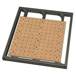
 [Adam Haile] has been spending some time improving his CNC router and his latest change is a custom wasteboard with improved bed support. Not only does the MDF wasteboard have plenty of threaded inserts to make for easy clamping solutions, but [Adam] replaced the frame underneath the board with a new set of aluminum extrusions to provide better support. Originally, there was only support for the edges of the wasteboard, which allowed the middle to sag. While researching the machine’s specs, he was able to recognize and order the exact extrusions he needed from Misumi and construct an improved bed to go with the new board. Should you wish to make your own version, [Adam] provides all the part numbers and CAD files required.
Embedded below is a video showing the machine drilling the holes, followed by surfacing the entire board so that it is flat. Since the bolt heads are well below the surface of the board, and the threaded inserts for the holes are on the bottom, there’s no worry of the tool hitting anything it shouldn’t during this process.
Why so many holes? Work holding is an important part of CNC operations, and lots of threaded holes gives the operator plenty of options to use different clamping solutions, like these scratch-made toe clamps.


More machines should have googly eyes installed.
I did something similar on my 3040 Chinese model. I can’t figure out the best method to remove the installed bed and keep rigidity, so I still have the aluminum spoiler board in place.
I used slots instead of a number of holes. The holes make more sense since it would keep the material more rigid. The advantage of slots is that I can slide the T nuts I had underneath into place and got some amount of adjustment.
While passing over the material to get it to be perfectly flat, if you use a spoiler board on top of that and then the item you’ll be machining, there’s no guarantee the surface will be flat with those additions.
Need a laser scanner to check for surface irregularity and apply that to the G Code. Anyone know of such a thing…cheap version please.
Laser scanner sounds a little excessive… I made a mount for a dial indicator and use that to check flatness. It’s not linked back to the control software or anything, but I imagine you could rig up an automatic probing system to probe 256 points or something.
3D printers have bed probing, my marlin software probes 9 points and uses that we printing to stay on the same relative position of the bed surface. Since i have an aluminium bed on my 3D printer it uses a hall sensor for the probing, but mechanical, probes with a switch are also available. I suppose that the number of points would be easilly extendable, didn’t check the firmware for that.