It’s fair to say that building electronic gadgets is easier now than it ever has been in the past. With low-cost modular components, there’s often just a couple dozen lines of code and a few jumper wires standing between your idea and a functioning prototype. Driving stepper motors is a perfect example: you can grab a cheap controller board, hook it up to a microcontroller, and the rest is essentially just software. But recently [mechatronicsguy] wondered if even that was more hardware than was technically necessary to get the job done.
 It’s not that he was intentionally looking to make things more complicated for himself, of course. His rationale was entirely economic; if you’re looking to drive a dozen or more stepper motors, even the “cheap” controllers can add up. So he started to wonder if he could skip the controller entirely and connect the stepper motor directly to the digital pins of an Arduino. Generally speaking this is a bad idea, but if you’re careful and are willing to take the risk, [mechatronicsguy] is living proof it’s possible
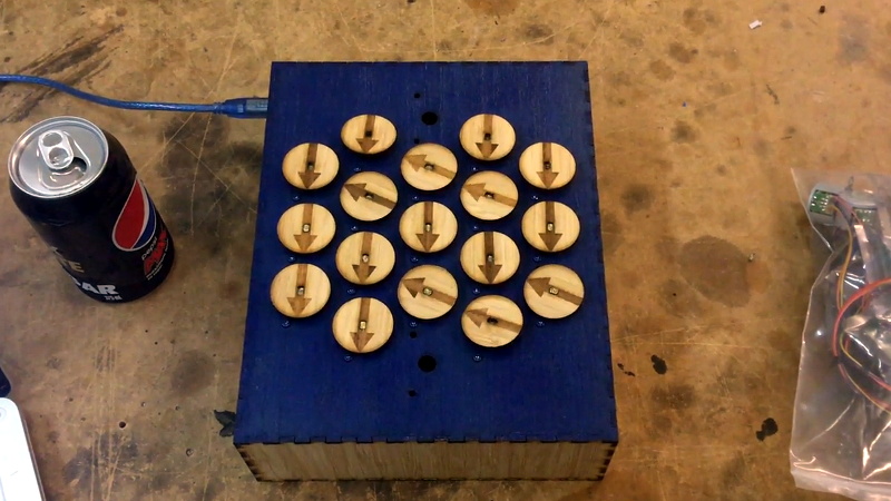
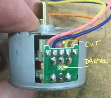
So what’s the trick to running a whopping seventeen individual stepper motors directly from the digital pins of an Arduino Mega? Well, to start with you’re not going to be running the beefy NEMA 17 motors like you might find in a 3D printer. [mechatronicsguy] is using the diminutive (and dirt cheap) 28BYJ-48, a light duty stepper used in many consumer products. Even with this relatively tiny motor, you need to crack open the case and cut a trace on the PCB to switch it from unipolar to bipolar.
Beyond that, you need to be careful. [mechatronicsguy] reports he’s had success running as many as ten of them at once, but realistically the fewer operating simultaneously the better. This is actually made easier due to the relatively poor specs of the 28BYJ-48 motor; its huge eleven degree step size means its not really susceptible to the same kind of slippage you’d get on a NEMA 17 when powered down. This means you can cut power to all but the actively moving motor and be fairly sure they’ll all stay where you left them.
With as popular as the 28BYJ-48 stepper is, there are several projects this “quick and dirty” method of interfacing could potentially work with. This small “barn door” star tracker is an obvious example, but we’ve also seen some very nice robotic arms built with these low-cost motors which could benefit from the technique.


Whilst no extra hardware at all is attractive, at £0.51 (60 cents?) per chip (£0.25 per motor) the ULN2803 will drive steppers at up to 50V / 500mA in Unipolar mode at very little cost. (and avoids the need to modify the motors)
Actually, I don’t know why he needed to modify the motors as the referenced site appears to be down.
If you have more time than money, you can buy bags full of jellybean transistors (cheapest PNP & NPN) and implement a transistor buffer on a strip board:
http://www.ermicro.com/blog/wp-content/uploads/2010/11/trsw28.jpg
Dead-bugging a ULN seems easier, though. And doesn’t that schematic require twice as many GPIO pins as the unipolar ULN approach?
Not really, seeing that the transistors are paired PNP-NPN which is a complementary pair. You can tie the input pairs together into one IO pin as long as you make sure it always has a defined logic state. Having them separate just allows you to drive the bridge into a hi-z state where the motor is free-wheeling.
More time than money…
especially the time it would take to find “matched pairs” in jelly bean transistors!
B^)
@Luke: > it always has a defined logic state.
if the bases are tied together without a defined state, both NPN/PNP transistors would be ON as their B-E junctions are forward biased. This can happen during power on until the firmware establish the I/O pin to output mode. When both pairs of transistors are ON, you have shorts across the power rails. This can cause issues if the uP power supply results in under-voltage as a result of the droop oof the power rail due to excess current.
@Ren: They don’t have to be ‘matching pairs’ – only need to be NPN/PNP switching transistors. You are building drivers not amplifiers.
> This can happen during power on until the firmware establish the I/O pin to output mode.
Hence why you force a state with a pull-up that is sufficiently small compared to the base resistors, but not so small you can’t drive it with your micro.
Ren, you do not need really matched pairs. These transistors are driven purely digital.
Although unipolar drive would make so much more sense, because you need half the transistors.
http://ebldc.com/wp-content/uploads/2010/09/UnipolarMotors.jpg
You need a fifth one to switch the VCC line to individual motors, so you can share the control lines with many motors, but that’s basically all you need. A bagful of NPNs costs very little.
Have you managed to read the original article (I can’t get to it). I am trying to work out why he needed to switch from unipolar to bipolar. (and normally that just means ignoring a wire, not cutting a link)
Because you can’t drive a unipolar motor directly with the Arduino.
Suppose your unipolar motor is connected with the common terminal to VCC, and your IO pin is set low. Then you lift the logic state high to stop the current through the coil. The coil will try to keep the current going in the same direction, so it appears as if a battery was connected with the negative terminal to the VCC and the positive terminal to the IO pin – it forces a surge of current through the IO pin and out the VCC pin of the Arduino back into the battery – repeat that a few times and the magic smoke comes out.
>Then you lift the logic state high to stop the current through the coil.
Or you can tristate the I/O so that it works just like the external MOSFET.
>The coil will try to keep the current going in the same direction
The inductor tries to maintain the same *magnitude* i.e. polarity & value. So if you inject 20mA, it would still be at most 20mA and decay from there. There is no *current* surge, only *voltage* surge.
The damage is from *voltage* generated from the di/dt as the stored energy from the inductor tries to force current through the now open circuit. Use a freewheeling diode for the decaying current to flow.
The issue is that the IO pin protection diodes in the Arduino aren’t built to handle 20 mA load dumps repeatedly. When you add a freewheel diode, whether or not it actually protects the arduino depends on which has the smaller threshold voltage, because the Arduino’s built-in diode is already acting as the freewheel diode in the circuit so it’s just a parallel path for it.
@Andy, yes it’s true, even if the two windigs are connected (5-wire connection) the voltages at the midpoints are nominally equal.
@Luke, the datasheet of the Atmega2560 states a “max. DC current into any IO pin” of 40mA. There is no further restriction of operation mode, like input or output. So I see current through the clamping diodes as included in the specification. If you really want, you can use Schottky diodes in parallel with the internal clamping diodes. It also works, if you don’t switch the output “hi-Z” but to the H logic state. The output transistor is a MOS transistor, it conducts also reverse current without any problem, as long as it is switched on by the correct gate voltage. I do this regularly, e.g. with a reverse polarity protection transistor. It effectively bridges it’s internal diode to reduce losses.
Oh, and if you switch the VCC line to the unipolar stepper at a sufficiently high rate, the coil acts as a filter and limits the current to some semi-continuous value. You just need a diode across the coil to provide the return path. That way you can switch between the steppers rapidly, much faster than your actual stepping pattern, and they’ll behave as if you were powering them continuously – they’ll have some reduced holding torque that corresponds to the duty cycle of your switching.
Some PNP (or p-channel) and can matrix many uni cheaply with the sme quad of npn(nchannel). Yup. Also add two more transistors and can drive full step with two i/o plus one for each uni. Lazy could use 4-16 decoder to drive 16 with 4+2 and probably one enabler. On the other 4988 step sticks are about as cheap as a single (uln)2803 or 2808. Small quantities anyway. So back to bipolar if wanted and could drive at ridiculous precision which would hardly be utilized by the 28byj. For reference the original prototyper felt it was necessary to increase the resistance by converting to bipolar. Additionally I have noticed some of 28byj have their phase wires switched/flipped at the motor side lately. So if scratching the gray check that. Seems cheap supplies of 28byj come with 2803 driver board each unit -5VDC version anyway.
Not feeling this project worthy.
Uln2003 not 2808 damnit. Not that it couldnt be used.
He mentions increased resistance, but there’s also increased torque per mA. He needs every bit of it with only 20 mA available.
Are there not PLC type Arduinos or Arduino shields that allow you to drive more current per output and also protect the output pins from shorting or overcurrent?
A fuvkinh ULN2903A
A “fuvkinh ” ancient part with darlington outputs -> about 1 volt drop at each output transistor. OK for 12V systems, somhow OK for 5V, but quite useless in a 3V system. Why is there no MOS replacement for this part? OTOH eight SOT-23 FETs use less space than the legacy DIP package. Four SOT-363 dual FETs use even less space than an SO-16.
If you buffer with a ULN**** then you can run the motors at any voltage you like up to 40V. This is another advantage, you are not limited to running the motors at IO logic voltage.
But there is no point discussing this in too much detail. The point of this article and thread is that you can run a stepper with no interface at all, or with cheap darlington arrays, slightly less cheap step drivers, all the way if up advanced closed-loop systems running at 100+V and hundreds of watts.
This article adds a useful bookend of zero part count.
I have some 6mm dia steppers with a linear guide. I can see this driving those very well.
Aside from ridiculous robots and other silliness. This seems like one of those things where one could manufacture an incredibly cheap semi-functional 3D printer at toy prices. Controlling 4-6 motors seems reasonable, and one could avoid issues with driving a hot end by using UV resin and a curing syringe extruder.
You’re not going to drive a printer with those motors, especially not when the current needs to be sourced from the Arduino!
Several 3D printers use those motors, including the Hero101. They’re not a _good_ choice for a printer, but they certainly work.
The silly thing is though, that he bought the steppers with the “drivers”, which is usually an ULN2003 for this motor. He also paid $3 for each motor + driver, while if he had bothered to look at Ali he could have bought the motors (without driver boards) at < USD 1 a piece.
I also can not see any sort of schematic on his site, so no idea why he modified the motors to bipolair (which would still need 4 pins per motor)
If you want to do anything with this type of motor, beware that you can buy them with different voltage ratings and gear ratios. They are NOT all the same!
And that these motors stay where they are is completely due to their gears, and not to the low pole count. They may have a relatively high detent torque, but that also does not have anything to do with the pole count. If they have it may be by their cheapness, or even by design. Detent torque is usually seen as a negative property and minimised. I do have some old steppers (scavanged from 30+ year old printers which have low pole count and almost no detent torque.
Literally every single thing you mentioned is addressed in the guys post, even the ability to buy them cheaper without the driver.
Did you even bother to read it before making this comment?