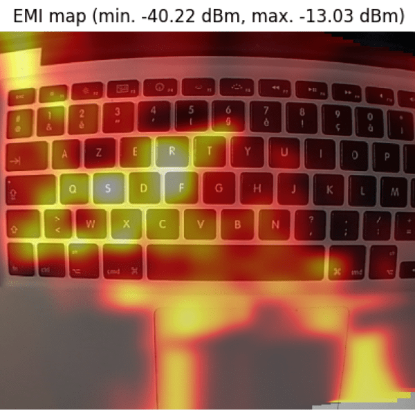
It’s one thing to know that your device is leaking electromagnetic interference (EMI), but if you really want to solve the problem, it might be helpful to know where the emissions are coming from. This heat-mapping EMI probe will answer that question, with style. It uses a webcam to record an EMI probe and the overlay a heat map of the interference on the image itself.
Regular readers will note that the hardware end of [Charles Grassin]’s EMI mapper bears a strong resemblance to the EMC probe made from semi-rigid coax we featured recently. Built as a cheap DIY substitute for an expensive off-the-shelf probe set for electromagnetic testing, the probe was super simple: just a semi-rigid coax jumper with one SMA plug lopped off and the raw end looped back and soldered. Connected to an SDR dongle, the probe proved useful for tracking down noisy circuits.
[Charles]’ project takes that a step further by adding a camera that looks down upon the device under test. OpenCV is used to track the probe, which is moved over the DUT manually with the help of an augmented reality display that helps track coverage, with a Python script recording its position and the RF power measurements. The video below shows the capture process and what the data looks like when reassembled as an overlay on top of the device.
Even if EMC testing isn’t your thing, this one seems like a lot of fun for the curious. [Charles] has kindly made the sources available on GitHub, so this is a great project to just knock out quickly and start mapping.
[via RTL-SDR.com]


This could be the basis for a bluetooth device and a phone App to find wires in walls. Also for an improved “toner” system like the ones used for tracing phone and ethernet cables.
Awesome! Thanks for sharing! Get’s me thinking about Radio Astronomy and Microwave imaging also. Great timing with the EMI probe build too.
Reminds me of doing similar overlay with an IR thermometer and as noted on Hackaday:
https://hackaday.com/2013/01/03/an-absurdly-clever-thermal-imaging-camera/
https://hackaday.com/2017/01/19/diy-thermal-imaging-done-low-tech-style/
Found some references to a question I asked that is related to this though and makes a better reference:
https://www.quora.com/What-test-equipment-have-you-made-with-the-SDRplay
This is brilliant!
That is very cool, there is something ‘magical’ about closing the loop between something you are waving around in space that is taking measurements and graphing that out on an picture (sort of like thermal cameras do but with no parallax error.) This takes a lot of guess-work out of emi probing.
Surprised they didn’t toss an IR led into the middle of the loop to assist in tracking, but must have a clean power supply so you don’t start measuring it of course.
Maybe just a reflective target on the probe and the IR LEDs mounted away from the board instead?
This is really cool and I want to put one together soon. I’ll have to see if I can get his code to work with the SDRPlay I have gathering dust.
– Wonderful –
– the elegance of marrying a simple DIY loop of copper wire (that Maxwell wouldd have understood), -> OpenCV via SDR – brilliant!
– reminds me of Youtube’s Mr Carlson’s Lab ‘Super Probe’:
https://www.youtube.com/watch?v=uVkJqqZroN0
– &, technique is surely applicable to mapping other phenomena- heat, SPL, gas etc etc
– On the road to a real Tricorder??
What a cool project! And dang useful for anybody working on an FCC EMI cert.
I think the next step is to make a flatbed with two XY motors that controlled via an Arduino and a usb port. This will solve the issue of the probe distance from the target and also automate the process.
Also a 3D map can be obtained. What I mean is that the 2D image now shows the hotspots but you can’t tell the frequency from that. By using the rtl-sdr API you can scan the same spot for a wide range of frequencies and then create a 3D map that also contains the frequency information. Tbh, it’s just a flash idea and I don’t got all the details yet toy head.
Anyway, the automated XY flatbed would be the next logical step, I think
Like such:
https://www.mdltechnologies.co.uk/manufacturers/emscan/
It’s mostly solid state, but can shift the sensors array slightly to interpolate.