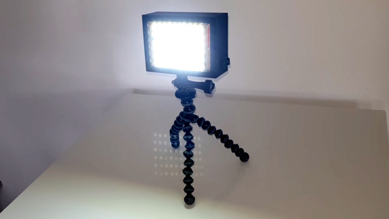
It’s now possible to source chip-on-board LED modules that have huge light output in a simple, easy to use package. However they can have major power requirements, and cheaper modules are also susceptible to dead spots. [Heliox] put together a great LED lamp design the old-school way, showing there’s more than one way to get the job done.
Standard SMD LEDs are the order of the day here. The LEDs are laid out on protoboard in neat rows, making them easy to solder in place. This also makes power distribution a cinch, with the copper traces carrying the power to each row. Power is courtesy of 18650 lithium batteries installed in the back of the 3D printed housing. A GoPro-style mount is printed as part of the case, allowing the lamp to be easily mounted in a variety of ways.
It’s a quick, cheap and easy way to build a versatile LED lamp. With a diffuser installed and integrated USB charging, we could see this making an excellent portable device for on-the-go videographers or technicians. We’ve seen [Heliox]’s LED creations before, too. Video after the break.


Thanx for sharing this great hack!
If I may ask, why don’t you use a limiting resistor on this board?
She uses an LM2596 constant current supply board, about $7 on Prime, and so doesn’t need one. No current limiting resistor means this is more efficient as well.
Two issues here.
She disconnects the power with her switch *after* the constant current source. That means the constant current supply is always active. The switch should instead be on the power side.
The voltage drop across cheap, bulk SMD LED’s is not constant, and she’s paralleling them. If you do this, the voltage drop at the rated current should be balanced for each group of LED’s so you don’t end up killing the strong ones and under-driving the weak ones. Better quality LED’s behave better in this regard as they are closer to spec out of the box, but something to think about.
The 2596 module she uses is constant voltage, not constant current – there is a CC/CV version of these modules (two trimpots) but she is not using it.
She’s under running (operating below the rated forward voltage) the leds considerably, looks like 6 in series, at a typical forward of 3v that would normally be 18v required forward voltage, but you can see she sets the voltage to about 10v.
Ugh, correction (HAD, please, edit feature) I watched again of course it’s 3 in series, for about 9-10v fwd, she’s still setting it probably a little under.
Ah.. You are right.
The french Amazon page she linked has that buck converter listed as CC-CV, for the CV version. And of course I skimmed the video as I don’t know French.. :)
That is really great. Definitely my favorite kind of hacks: Cheap, easy, useful, and not too crusty all in one.
I would bet that most of us that read this will some at point in the future remember this and impulse build one with a pile of leftover LEDs.
And how good of a heat sink is unventilated protoboard?
I have a 220 lumen, single LED flashlight with insufficient heat sink. If you bump it after it’s been on for a while, the diode slides off of the softened solder.
great setup here, gives me ideas for grow lights.
I was taught to never run leds in parallel, without some kind of current limiting for each led.
Basically – if leds differ a bit and current limiting is done for the whole set – one led gets more current, because it has a bit different I/V curve, gradually burns out. Then other leds follow.