The first step to reducing the energy consumption of your home is figuring out how much you actually use in the first place. After all, you need a baseline to compare against when you start making changes. But fiddling around with high voltage is something a lot of hackers will go out of their way to avoid. Luckily, as [Xavier Decuyper] explains, you can build a very robust DIY energy monitoring system without having to modify your AC wiring.
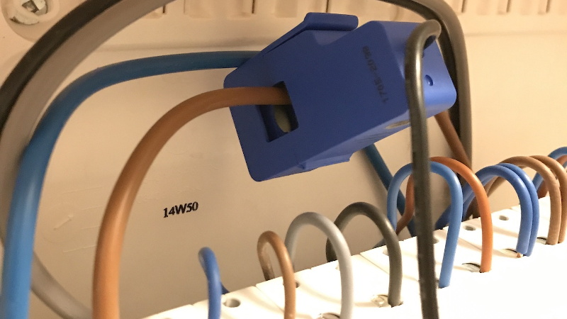
 In the video after the break, [Xavier] goes over the theory of how it all works, but the short version is that you just need to use a Current Transformer (CT) sensor. These little devices clamp over an AC wire and detect how much current is passing through it via induction. In his case, he used a YHDC SCT-013-030 sensor that can measure up to 30 amps and costs about $12 USD. It outputs a voltage between 0 and 1 volts, which makes it extremely easy to read using the ADC of your favorite microcontroller.
Once you’ve got the CT sensor connected to your microcontroller, the rest really just depends on how far you want to take the software side of things. You could just log the current consumption to a plain text file if that’s your style, but [Xavier] wanted to challenge himself to develop a energy monitoring system that rivaled commercial offerings so he took the data and ran with it.
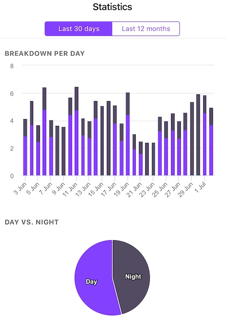
A good chunk of his write-up explains how the used Amazon Web Services (AWS) to process and ultimately display all the data he collects with his ESP32 energy monitor. Every 30 seconds, the hardware reports the current consumption to AWS through MQTT. The readings are stored in a database, and [Xavier] uses GraphQL and Dygraphs to generate visualizations. He even used Ionic to develop a cross-platform mobile application so he can fawn over his professional looking charts and graphs on the go.
We’ve already seen how carefully monitoring energy consumption can uncover some surprising trends, so if you want to go green and don’t have an optically coupled electricity meter, the CT sensor method might be just what you need.


And for those who may be more inclined to measure real power (as opposed to just measured current times the average line voltage), and aren’t afraid to connect some (optoisolated) components to the line directly, the Woodward power meter is a very clever and simple technique that uses a quad optoisolator as the sensor.
Originally from Woodward’s article in EDN in 1994, here’s a more accessible Nuts & Volts article about it (pdf): http://beet.the-eye.eu/public/Books/Electronic%20Archive/BuildADigitalWattAndWatt-hourMeter.pdf that also goes through the theory very nicely.
(It also doesn’t depend on the whims of far-away computers to deliver your data to you either but, well, that that’s just, like, my opinion, man.)
Nice link thanks.
Takes me back to the 68705P3 we used for quadrature decoding driving 4 large red 7 segment leds for end stop positioning on press brakes circa 1986, nice chip for the time, the quadrature done by 74c86, cheers
Woodward has an Interesting circuit. It is amusing that he states the optos should be kept away from drafts when it is being calibrated. I would want it to provide accurate readings as well. It seems there is a lot of potential error in the way he deals with the analog. I suspect it is more accurate but at the same time, and as he states, it takes a different set of magic values for 220 or higher operation and this simply measures current and assumes voltage so it should be able to move to different voltages with ease. The other big Q is weather your average home owner is looking for accuracy or just ferreting out the big loads. I know I rarely put my Kill A Watt in the “price” mode, but use at both my place and friends places to see what the big loads are. It is sad it is limited to 120V. FWIW I have a bunch of real KWH meters just like the power company but they are big to deploy, and not user friendly to read. Still they are the gold standard. They are what the utility uses.
Maybe throw some machine learning at the problem of load differentiation.
The “Sense” energy meter product does this. Judging by amazon reviews, its effectiveness at distinguishing loads is middling at best. Of course, if you could train it by “real power at load” vs “real whole house power” for an extended period of time, it’d probably get pretty good. But then that would defeat the purpose, wouldn’t it.
I believe there is a project out there that does just that. The name escapes me at the moment.
I really like the method used here: https://www.mousa-simple-projects.com/2017/12/power-factor-measurment-using-arduino_18.html
It uses two [op-amp] comparators that select the zero crossing of the voltage (via small voltage transformer) and current (via current transformer) waveforms and XORs them. Your microcontroller just reads the pulse width to determine powerfactor. Brilliant!
Add another couple of op-amps to scale up/down the voltage and current waveforms into their respective ADC input and, walla, record both real and reactive power!
Cute method of getting a quick & dirty phase difference measure. It only measures the first harmonic, but unless you’ve got non-linear loads, like switching power supplies, it would give reasonable measurements after calibration for offsets and lag in each channel. If all you want is that, great. Nice and simple.
But you can do better, and even with fewer active components: just omit the XOR gate, replace the comparators with opamps, and feed the two amp outputs into ADCs. Even a lowly Arduino Uno is more than capable of capturing two channels at more than a kilohertz: enough to capture 17 harmonics, like a real grown-up power meter does.
It might be a challenge to do the arithmetic and communication as well in an Uno at that rate, but I know a Teensy 3.2 can easily do it, at half the price.
Hmm. It looks to me that that circuit can’t distinguish between leading and lagging power factor.
FYI:
– looks like mousa-simple-projects is hijacked by an advertiser
– the word you’re looking for is voilà – definitely not how you’d spell it if you’ve only ever heard it before!
I dont think its limited to 120v Just scale R4 accordingly, isn’t it ?
This looks to be nicely written up. I recently completed a similar project, but used an ESP8266 and an external ADC for added resolution. I’m on the North American grid, so I used two CTs to “read” both buses.
In my case, the ESP8266 measures total current flow every 10 s and sends the data via MQTT to a Raspberry Pi, on which I have Node-Red sending the data to an InfluxDB database as well as to Thingspeak. A bit of a mashup of different systems. I’d love to be less reliant on the Raspberry Pi (and its potential for corrupted SD cards, etc.) but haven’t yet figured out / decided what to do on that front.
Hi Joe, what external ADC you use ?
ADC inside esp8266 and esp32 not linearity and effect by vcc, temperature.
I used an MCP3208. It is a 12-bit ADC that is pretty inexpensive, and communicates with the ESP via SPI. It took a bit of tweaking to get it to work properly (the voltage divider resistors need to be fairly small, e.g. 1 kOhm, to get it to read correctly) but it is fast and gives higher resolution than the ESP8266.
Hi, Joe! What modifications can be done in order to use two CTs?
There needs to be a browser plugin to automatically block any video or post that uses the phrase “watts per hour”.
Cripes. I don’t think there’s a better way to instantly discredit the whole video.
(the the alt-energy and RV folk are even worse, saying non-sensicals like “amps per day” routinely)
Yes, I find misuse of units to be a great way to determine whether the writer or speaker has a clue.
Watts per hour makes perfect sense to me
Watts per hour makes sense if you are describing how fast power consumption changes.
If you are using “Watts per hour” it in the place of “Watts” or “Watt-hours per hour”, then you are ignorant and have a fundamental misunderstanding of how electricity and the universe in general works: You are instantly identified as incompetent.
Fortunately, that’s easily repairable by reading any introductory material on the subject, or even just sitting and thinking for a moment or two.
Misunderstanding the units hardly implies misunderstanding anything else. Take it easy.
hardly implies misunderstanding anything else Perhaps. But when you are trying to measure something and don’t understand even the units it is measured in, it does raise the question of what else you don’t understand about it. All the pretty ESP32 and AWS etc. lipstick you apply after doesn’t change that, no matter how competent you are with those parts.
If you can’t use the right units for energy and power, you shouldn’t be writing educational articles on the internet
Actually Watts per hour is a unit. I just don’t know when we would want to know the hourly rate of change of power Joules/Second/hour haha
The only legitimate use for ‘amps per day’ is if it is in reference to Yngwie Malmsteen trying to break his Sandvik guitar.
Measuring current alone is not a very good indicator of power usage, unless you have only resistive loads (unlikely in a modern home). Believe me, I’ve tried.
I’ve side-stepped the problem of actually sensing the line voltage by assuming that it is a perfect 230V sine wave, and detecting the phase with a zero-crossing detector (conveniently, it was already present in the design).
Looking at the wiring picture, It seems you have 3 phases. If you plan to map all of your consumption, you’ll have to use clamps for the gray and black wire as well.
It’s a nice project. CT sensors aren’t really that accurate, but you still get a useful indication.
I built a system using a CurrentCost EnviR, using three sensors, and a Raspberry pi to capture to power measurements.
Now, I’d probably go with this:
https://openenergymonitor.org/
CT sensors can be very accurate if the system is calibrated properly. Crack open any digital power meter that power companies are now using and you’ll find they now use a CT. CTs have also long been used in metering large power loads. Look at the power feed of any large industrial warehouse and youll probably see all the phases running though a set of CTs and those are then wired down to a power meter, rather than running all that current though the power meter itself.
Don’t most utility meters use the dreaded Rogowski coil which amplifies high-frequency components? So if you have a lot of harmonics, your bill can go up unfairly.
No. They don’t. And no, it won’t.
I’m thinking of doing something similar with my Current Cost clamps, but using an ESP8266. Are you willing to share any details of how you set this up? Do you know the number of windings in the clamps?
Just use a modbus din rail meter from the usual chinese sites, they report several different measurements from a single sub 30$ part
…or you can buy an efergy with 1x3phase main meter and up to 4 sub meters one of them for power production like photovoltaic.
Just to be clear: these cheap CT sensors measure power as accurate as your thumb measures distance. And to measure power every 30 seconds is also pointless. It tells you only that there is something using energy. Not even how much. And the chance you are missing something is pretty high.
An energy meter is measuring with 20MS/s and up AND is measuring the voltage and can be bought from China for 20 bucks. Yes – even a MODBUS meter.
Just to be clear: A CT sensor is only as good as its signal conditioning circuit and its implementation. It’s not the fault of the transformer that you find them not accurate.
The ‘circuit’ described in the linked article is an excellent and woefully-common example of how NOT to implement it.
These cheap current transformers are just that: the transformer. If it’s not included, you need at least the correct size burden resistor. You also need an amplifier with excellent common mode rejection and/or good electrostatic shielding.
Most naive attempts at implementing these things forget that the 120V or 230V line you’re clipping on is capacitively coupled to the coil on that core: If the electrostatic shield is not grounded (or not present) there’s a massive common-mode signal on the wire pair coming out of it that will swamp the differential signal that represents the line current.
With decent signal conditioning, and staying within the designed operating range of the CT, they are both precise and accurate. Heck, it’s the standard way of measuring line currents in utility systems, all the way from gigawatt long-haul lines down to the newfangled smartmeter on the side of your house.
Have a look at any of the many energy meter IC datasheets and app notes for good descriptions of the principle of operation and how to properly implement a current transformer sensor. Random example: Maxim’s MAXQ3180
Also not a single word about how current transformers are dangerous if used improperly. Without the burden resistor, or if it fails, now you have thousands of volts on your dinky little wires… Best case scenario your micro is probably going to cook.
The inexpensive Chinese CTs have a shunt system consisting of two Zener diodes in place to prevent this situation from arising.
And if you want some greater accuracy. Take a look at this: https://www.crowdsupply.com/circuitsetup/split-single-phase-energy-meter/
IoTaWatt is an open source 14 channel ESP based true power energy monitor that I like. It solves many of the issues brought up here and has very nice documentation.
https://iotawatt.com/
I’m building a 12-channel power meter, using current transformers, in a DIN rail mountable enclosure. It uses an STM32 for ADC measurements and ESP8266 for networking, and it measures voltage simultaneously with current, and therefore I can derive real power and power factor for each of the channels. When the project is completed, I’d like to open-source it.
Just have your energy supplier fit a smart meter, does all the work for you and the free monitor shows you usage every second
@CJ, I have a Smart Meter on my house that PG&E (SF Bay area) that I’d like to connect to. PG&E says I can connect a HAN device (https://www.nts.com/services/certification/pge/han-devices/). CAn you or anyone else reading this point me to some HAN devices suitable for a software type like me to be able to read and analyze locally?
Safety is seriously overrated. It certainly doesn’t put people on the moon.
Hi, nice project ,
I’ve a similar project on the way for a solar power / grid setup.
My idea is to collect the voltage and current at the same time. I’m using 2 ACD’s of the ESP32.
With the speed of the ESP32 i can see the sine wav form on the voltage and current (for voltage I’m using a transformer, for current I’m using a CT). This allows me to measure the current on the 4-quadrants :).
The ESP code an provide a max / min value (at the max voltage what was the current). This will allow me to see it the current is positive or negative (if the house is consuming less that the generated solar panel the current will be negative). Or it can send a wave form subset for processing on a PC.
I’ll trie to produce some kind of document where its ready.
Regards
Hello, could you provide wiring diagram and resistors/capacitors used to read positive and negative values?