You’d think that something made out of glass and epoxy would transmit a decent amount of light. Unfortunately for [Jeremy Ruhland], it turns out that FR4 is not great light pipe material, at least in one dimension.
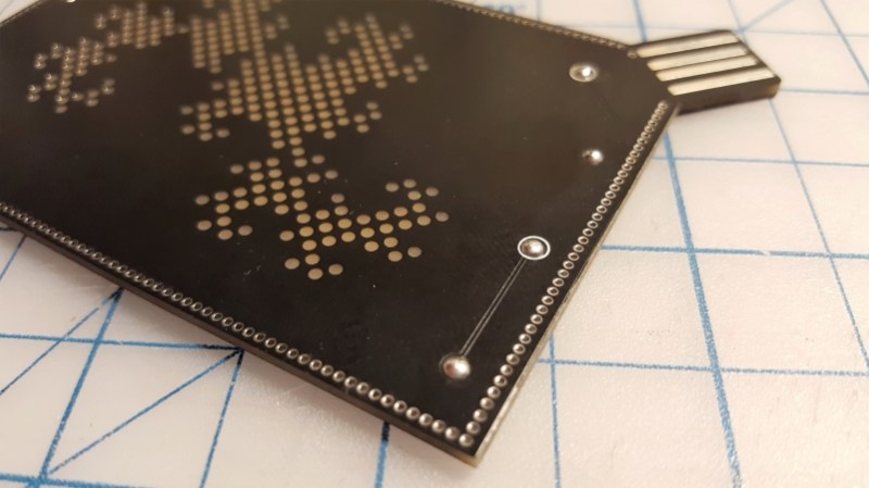
The backstory on this has to do with #badgelife, where it has become popular to reverse mount SMD LEDs on areas of PCBs that are devoid of masking, allowing the light to shine through with a warm, diffuse glow – we’ve even featured a through-PCB word clock that uses a similar technique to wonderful effect. [Jeremy]’s idea was to use 0603 SMD LEDs mounted inside non-plated through-holes to illuminate the interior of the board edgewise. It seems like a great idea, almost like the diffusers used to illuminate flat displays from the edge.
Sadly, the light from [Jeremy]’s LEDs just didn’t make it very far into the FR4 before being absorbed – about 15 mm max. That makes for an underwhelming appearance, but all is certainly not lost. Valuable lessons about PCB design were had, like exactly how to get a fab to understand what you’re trying to do with non-plated holes and why you want to fence the entire edge of the board in vias. But best of all, [Jeremy] explored what’s possible with Oreo construction, and came away with ideas for other uses of the method. That counts as a win in our book.


Seems obvious to me considering bare FR4 isn’t transparent?
“You’d think that something made out of glass and epoxy would transmit a decent amount of light. ”
not when its piss yellow and 70% opaque, just look at it its a hardened fabric, I wouldnt expect it to transmit any more light than my t-shirt
Strange that one has to go this far to learn this much. It shouldn’t be difficult to take just any PCB, a LED and shine into its edge and see what happens?
That’s why it’s fail of the week, to remind us all that testing your assumptions on some cheap model or limited prototype will save you money and failed projects. It was very good read.
well, i agree completely. But, we must not forget how enthusiasm can clog the brain.
Sometimes, basic testing is done, but if it doesn’t produce the results we are expecting then we are sometimes eager to believe that it was caused by an inaccurate test setup. And that it all will work perfectly if we just make it right (sometimes forgeting OR ignoring the obvious). Sometimes the goal blinds us from seeing the truth until we hit that brick wall of confrontation and that we have to admit that it was a silly idea to begin with.
But, if it had worked, it would have been a different story.
Sometimes you need to do the things that seem impossible.
If you do the impossible and fail, then you are an idiot for trying, but if you do the impossible and succeed, you could become a hero. I write “could become” because in many cases it’s not the inventor of but the one who exploits it that claims the fame in the long run.
But never be scared to fail, it’s all part of the process. Sometimes great things come from failure, think of superglue, vulcanized rubber, corn flakes or Stainless Steel.
> why you want to fence the entire edge of the board in vias.
It is commonly done for multilayer board (>>2) for EMC to contain the RF energy within the inner layers.
http://lamsimenterprises.com/Controlling_EMI_Emmissions_From%20PCB_Edges_WhitePaper_iss01.pdf
the key here is “non-plated” holes rather than vias…
I wouldn’t quite call it a fail if there is something learned from the experimentation and entertainment derived from it. I’ve been playing with the whole pcb’s as light masks idea since I did the word clock and I’ve found something interesting but obvious in retrospect. You cant really get vibrant blue colors using commonly available fr4. The fr4 is a slightly yellow color and as you might guess blue + sort of yellow = crappy white that is faintly blue. I guess thinking about how white leds work with a blue chip and yellow phosphor should have made this obvious to me. Now maybe you can blast a high enough brightness of the blue to overwhelm the pcb but it wouldn’t be very practical for the matrix addressed leds I intend to make.
So, he wasn’t trying to light a pipe so he could smoke?
ceci n’est pas une pipe
Thank you!
I had no idea what that meant, so I Goofled…
https://en.wikipedia.org/wiki/The_Treachery_of_Images
B^)
My plumbing connection would be a lightpipe if I passed a radioactive stool.
Has anyone trying bonding a copper sheet onto acrylic and then etching it into a PCB? Granted, It’s (presumably) not something you could get a fab house to do for you (so, not great for mass-produced conference badges), but for low-volume, low-density DIY projects it seems like it might have potential. Besides controlled light transmission, another advantage it would have over FR4 and the like is that it could be laser cut (through non-copper areas) into any desired shape, and through holes could be laser drilled. It would also be easier & safer than with nasty FR4 to etch anything that shouldn’t go all the way through with a very simple, low-power CNC router. I’m thinking about trying this for making giant (like, 4×8′) PCBs for some lighting projects, and wondering if anyone else has already succeeded/failed with it.
It’s an interesting concept, but, honestly, I would just cut out whatever places I needed light to shine through, then either glue in pieces of acrylic or pour in resin. (Personally, I would use resin, as fiddling with little pieces of acrylic would be *FAR* too much of a pain in the… neck.)
While I may not b e the brightest bub on the string, but intuitively wouldn’t have expected much light to pass the through the fiberglass.. The fiberglas is either woven, or a tangled mat, with now way for light to travel the lenght of the glass fibers.
Uh.. Wouldn’t have expected NOT much light to pass. The Hackaday staff can edit their screwups, isn’t high time the visitors ae are able to do so as well? Without visitors hackaday has basis for existence. As I said before hackaday is a poor example for hackers, after an initial fail at an edit option, they seem to have given up.
Maybe drill holes the length of the fibreglass first? Fill with something with different characteristics, such as blue cure resin and light may outcouple more effectively.