
I find that if I’m trying to make a point with a student or a colleague about a circuit, sometimes the Falstad online simulator is worth a few thousand words. You can draw the circuit, play with the values, and even see the current flow in an intuitive way as well as make traditional measurements. The simulator not only handles analog but also digital circuits. At first glance, though, the digital functions appear limited, but if you dig deeper, there is a custom logic block that can really help. I dug into this — and into how switches work in the simulator — the other day in response to a Hackaday post. If you use Falstad, read on!
Childhood Memories
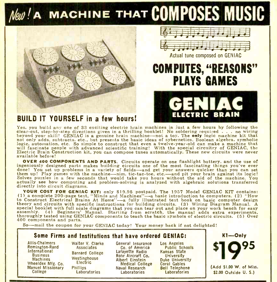 When I was a kid, I saw a computer advertised in the Layfayette catalog. It was the Geniac — the subject of a recent post about a recreation of the computer. My parents shelled out the $20 and I was excited. After all, the thing could play tic tac toe, compose music, and do other feats of wonder.
The problem is, no one that I asked — including an electrical engineer from the power company my Dad worked for — could figure it out. Keep in mind, I was probably 9 years old and back then very few people — even power engineers — were very computer savvy.
By the time I was a teenager, I realized the whole thing was a bunch of rotary switches you could configure as logic gates. By that time, though, the Geniac was long gone, a victim of Mom’s spring cleaning. A few years ago, I bought a mostly complete one on eBay but it needs lightbulbs that I haven’t replaced yet, but it is on my long list of things to do to get it working.
The Virtue of Shame
However, the Hackaday post shamed me into action. All these years and I haven’t built any of the circuits in the manual. I decided that I wanted to do that and since the post had a picture of the binary to decimal decoder, I thought maybe I could simulate it.
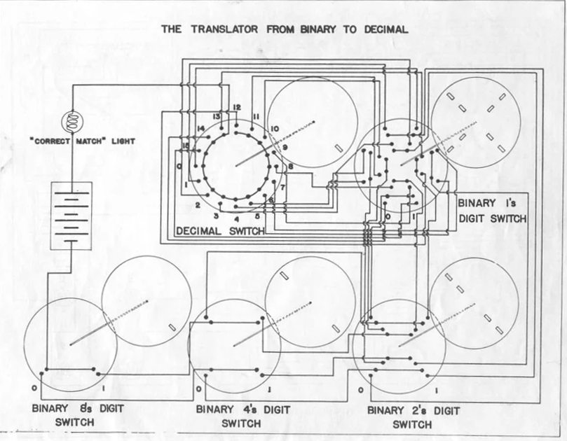
The key to understanding the diagrams in the Geniac manual is that you are building a multiway switch. So the binary 8s digit switch in the lower left of the diagram is a two-position switch. The binary 4s digit is DPDT switch. If you point at 0, the contacts at 7:00 and 1:00 connect. If you point at 1:00, the contacts at 5:00 and 11:00 short because of the brass staples in the upper disk. The decimal switch, on the other hand, is a single pole, but has 16 positions.
In operation, you dial in the binary number you want to convert and then turn the decimal switch until the light bulb turns on. This is a simple switch tree so that each binary number grounds one terminal of the decimal switch and since the lightbulb connects to the common, it lights up when you make that connection.
Falstad
There were two problems I had to tackle. First is making multipole switches in the simulator. There’s a way to do it, but also there’s a thing or two to keep in mind. The second issue was that I wanted to add a fancy display but a 16:1 decoder isn’t available. That’s how I got started with the custom logic block.
The switches are pretty easy to figure out. Under Passive Components on the menu there is an SPDT switch you can insert or you can use the uppercase S shortcut key. Of course, you don’t want a SPDT switch, but you have to start there. Once you place one on the screen, you can right click it and select Edit.
There are two fields in the resulting dialog box of interest. The number of throws is pretty obvious. For the decimal switch you can set that to 16. The switch group is the key to making multiple poles. Switch group 0 is special and means the switch is independent. However, if you set the group number to something else, all switches in that group will operate together. There’s no direct indication of that on the screen, though, like there would be in a real schematic.
Well, that’s not exactly true. Any switch that has more than one pole will show up as DP when you hover the mouse over it. So three switches in the same group with 16 throws will all show up as DP16T even though that’s not technically correct.
A Small Gotcha
The other thing I found by accident is that if you add a pole to a switch, you should make sure that the switch is in its default position and in the same orientation as the other switches in the same group. If you have the 16 position switch set to position 5, for example, and create a new switch set on position 0 then the switches will maintain that separation. That is, moving the first switch to position 6 will set the second switch to position 1. There might be times that’s a feature, but in general, it isn’t what you want. The real problem arises when you have the switches facing opposite each other. Then moving one switch up a position will move the other one down. Again, probably not what you want.
The switch has a way to set some sliders, but those sliders control the number of throws and the switch group for the switch so that’s not very useful. Probably the easiest thing to do is duplicate the existing switch to make a new pole.
Custom Logic
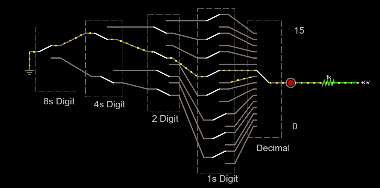
Armed with a way to make big switches like Geniac, it was pretty easy to set the switches up for the decimal converter. However, I wasn’t happy with it because the switches are hard to read. Falstad isn’t really made for 16 throw switches.
I wanted to take a second pole for the decimal switch and use that to drive a 7 segment display to indicate the position of the decimal switch. In order to do that, you need a 16 line to 4 line encoder but Falstad doesn’t have one that I could find.
You could build it out of logic gates, of course, but that would be tedious at best. But I noticed the block named custom logic (under Digital Chips) and that was the answer I was looking for.
When you place the block, you get a little box with a few inputs and an output. Right click and hit edit and you’ll see a box that lets you name a model to use for the function. Pressing Edit Model lets you change the function for blocks that use that model.
There are three defining fields in the dialog box. The first is the inputs separated by commas. You can use one or two character names. Another box contains comma-separated outputs using the same one or two characters. The box will redraw to fit the number of ports. There’s also an info text that shows up when you float your cursor over the box. The port names can also have a slash in front (like /Q) to indicate negative logic if you like.
However, the final field is the one you want. You can define your custom function using a simple syntax. Let’s take a simple example first. Suppose you wanted to build a block that was an AND gate with two inputs A and B. The output is C. The definition would be:
00=0
01=0
10=0
11=1
That’s it. In addition to 1 and 0 you can use + or – for a positive or negative transition. You can use pattern letters and you can use ? for a don’t care. For example, suppose you have a block that copies the first input (A) to the output if the Enable pin is true. If the Enable pin is false, you want to output a zero:
?1=A
?0=0
Or you could write:
00=0
01=1
11=1
The input string can be longer than the number of inputs. In that case, the simulator reads the outputs. This lets you build state. For example, the manual shows an SR latch with inputs S and R might have outputs Q and /Q:
??00=10
10??=10
01??=01
??AB=AB
The first line handles the reset condition so that /Q is always equal to the inverse of Q. It appears that in the definition you can name the outputs anything you want on the left and then use them on the right even if the port names are different (e.g., in this case, Q is A and /Q is B). That line could just as well read ??XY=XY. In the definition, you can’t use two characters including the slash.
The Final Product
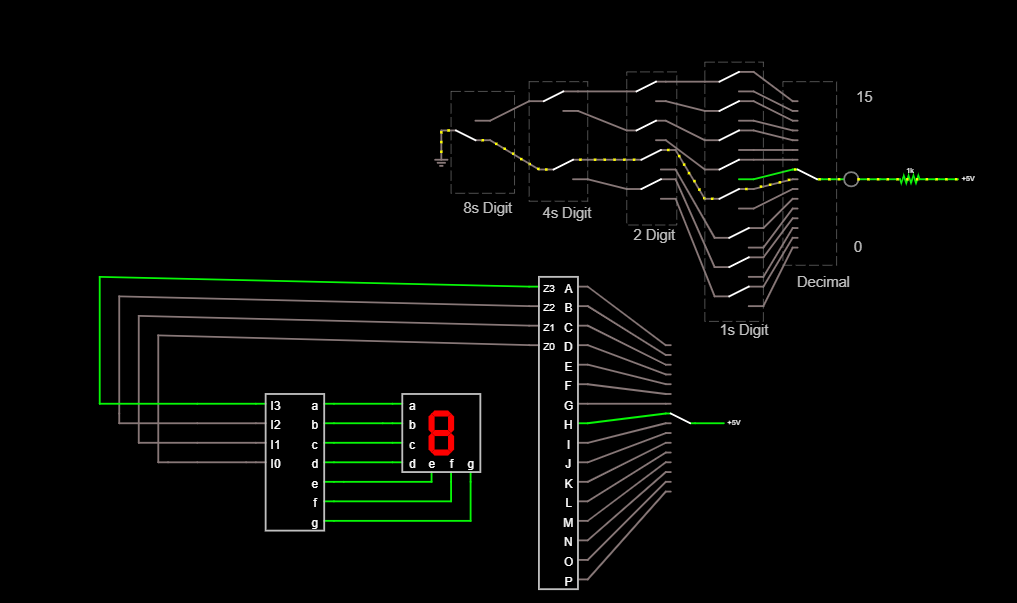
Now it is easy to create the decoder:
0000000000000001=0000
0000000000000010=0001
0000000000000100=0010
0000000000001000=0011
0000000000010000=0100
0000000000100000=0101
0000000001000000=0110
0000000010000000=0111
0000000100000000=1000
0000001000000000=1001
0000010000000000=1010
0000100000000000=1011
0001000000000000=1100
0010000000000000=1101
0100000000000000=1110
1000000000000000=1111
????????????????=0000
The rest is just a lot of wiring. Although the snake of switch connections isn’t as aesthetic as the Geniac disks, it serves the same purpose. It would be a lot of work, but you could probably do all the other Geniac programs in the same way by noting how many throws and poles each disk switch has.
There are actually better ways than the Geniac to do computing with switches. And if you want to do more conventional logic simulation with Falstad, try building flip flops.


That is awesome .. I love the Falstad simulator and have used it in the past to build simulations for educational purposes.
One particularly memorable “build” was to create an approximate model of a 4558 op amp. I had used the real thing in class to show that an op amp can be used as a comparator, and .. holy 541+! .. with certain voltages near the rails, it did the opposite of what you would expect.
So, I found a diagram of the 4558 internal circuitry online, and created a discrete parts simulation of the amp .. and it had the same issue.
Here’s a copy of the email to the class, and the Falstad circuit, for thems of yinz what take a shine to this sort of thing.
————————————————————————-
Very cool — I was able to find the schematic of a 4558 on the web and I reconstructed it in the circuit simulator (www.falstad.com/circuit).
The component values on the amp were just made up, because they were missing from the published schematic, but apparently the circuit is close enough to impersonate the weirdness that we saw when the “+” input gets too low.
Edit the voltage at the “+” input to 5.1 volts, the comparator goes high (as it should) — edit the voltage at the “+” input to 4.9 volts, the comparator goes low (as it should). Edit the voltage to 0.5 volts, the comparator unexpectedly goes high (as it does in real-life)! Definitely not ideal behavior, but very interesting … the root cause of this seems to be that the circuit starts dumping enough current back through the “+” output that it makes things go awry.
$ 1 5.0E-6 10.20027730826997 50 5.0 50
r 192 48 192 112 0 500.0
t 224 128 192 128 0 -1 1.9566294930421035 -0.5063807375045943 100.0
t 256 224 224 224 0 -1 5.0730456829789325 -0.4056782310760392 100.0
w 192 192 224 192 0
w 224 192 224 208 0
w 192 192 160 192 0
w 160 192 160 208 0
t 128 224 160 224 0 -1 4.472753560089531 -0.5056782310760388 100.0
w 256 224 256 256 0
w 256 256 96 256 0
w 128 224 96 224 0
x 102 218 128 224 0 24 “-”
x 98 284 130 290 0 24 “+”
w 224 240 224 320 0
w 224 320 240 320 0
d 240 288 288 288 1 0.805904783
w 240 288 240 320 0
c 240 320 288 320 0 1.0E-11 -8.062692421176575
w 288 288 288 320 0
t 192 400 224 400 0 1 0.500292122889401 0.5010969982358321 100.0
t 192 400 160 400 0 1 0.0 0.49200673033646214 100.0
w 160 240 160 320 0
w 160 320 192 320 0
w 160 416 160 432 0
w 224 416 224 432 0
w 160 432 192 432 0
r 160 432 160 496 0 1000.0
c 192 432 192 496 0 1.0E-11 0.03523970957400622
r 224 432 224 496 0 1000.0
w 192 320 192 400 0
w 160 320 160 384 0
w 224 320 224 352 0
w 224 352 224 384 0
w 224 352 288 352 0
t 288 352 320 352 0 1 -7.973045682978933 0.026954315551415895 100.0
w 288 320 352 320 0
r 352 320 352 224 0 39000.0
t 400 224 432 224 0 1 0.0898954269420269 -6.91183714707222E-8 100.0
t 384 192 352 192 0 1 0.0 -0.0898954269420269 100.0
w 400 224 352 224 0
w 384 192 432 192 0
t 400 128 432 128 0 -1 -0.5374435180191011 -0.5376922758818576 100.0
w 192 144 192 192 0
w 224 128 400 128 0
w 432 144 432 160 0
w 432 192 432 208 0
w 352 208 352 224 0
w 352 176 352 160 0
w 352 160 432 160 0
w 432 160 432 192 0
w 320 336 320 48 0
w 432 112 432 48 0
t 464 160 496 160 0 1 -2.4875786275657674E-4 0.010054676167154497 100.0
w 496 144 496 48 0
w 432 160 464 160 0
r 496 176 496 224 0 25.0
r 496 224 560 224 0 75.0
r 496 224 496 304 0 50.0
w 352 320 432 320 0
w 432 320 464 320 0
w 432 240 432 320 0
t 400 400 432 400 0 1 -8.08964673672799 1.4696514946850592E-9 100.0
w 432 320 432 384 0
w 320 368 320 400 0
w 320 400 400 400 0
t 544 128 576 128 0 -1 0.0 -0.5376922758818576 100.0
w 400 128 544 128 0
w 576 112 576 48 0
w 544 128 544 160 0
w 544 160 576 160 0
w 576 144 576 160 0
r 320 400 320 496 0 5000.0
w 432 416 432 496 0
t 464 320 496 320 0 -1 8.089646738197642 0.09995017223130453 100.0
w 496 336 496 496 0
w 576 160 576 304 0
t 608 320 576 320 0 1 -3.5772948066198365 0.5482069968833607 100.0
r 576 336 576 496 0 10000.0
j 640 256 608 256 0 -4.0
w 608 272 608 320 0
z 608 496 608 320 1 0.805904783 5.6
w 640 256 640 496 0
w 608 240 608 48 0
w 560 224 672 224 0
w 608 48 576 48 0
w 576 48 496 48 0
w 496 48 432 48 0
w 432 48 320 48 0
w 320 48 192 48 0
w 192 48 96 48 0
w 640 496 608 496 0
w 608 496 576 496 0
w 576 496 496 496 0
w 496 496 432 496 0
w 432 496 320 496 0
w 320 496 224 496 0
w 224 496 192 496 0
w 192 496 160 496 0
w 160 496 112 496 0
R 96 256 64 256 0 0 40.0 5.1 0.0 0.0 0.5
R 96 224 64 224 0 0 40.0 5.0 0.0 0.0 0.5
g 112 496 112 528 0
R 96 48 64 48 0 0 40.0 8.0 0.0 0.0 0.5
Using the custom logic block, I made a a block that you can set to behave like all 8 logic gates. BUF and NOT can be simulated with OR with the Inv pin either
it has 6 input pins:
Inv,AND,OR,XOR,I,I
and 1 output:
O
It is controlled by 2 switches: a normal switch going to Inv, which you can turn on to invert the output to simulate the ‘N’ logic gates; and a 3-pole switch going to AND, OR, and XOR
The I pins Can be input by anything you choose, And because the basic logic gates are symmetric, The I pins don’t have to be differentiated between, thus them having the same name.
The logic definition is:
#AND
0 100 11=1
0 100 ??=0
1 100 11=0
1 100 ??=1
#OR
0 010 00=0
0 010 ??=1
1 010 00=1
1 010 ??=0
#XOR
0 001 aa=0
0 001 ??=1
1 001 aa=1
1 001 ??=0