When building robots, or indeed other complex mechanical systems, it’s often the case that more and more limit switches, light gates and sensors are amassed as the project evolves. Each addition brings more IO pin usage, cost, potentially new interfacing requirements and accompanying microcontrollers or ADCs. If you don’t have much electronics experience, that’s not ideal. With this in mind, for a Hackaday prize entry [rand3289] is working on FiberGrid, a clever shortcut for interfacing multiple sensors without complex hardware. It doesn’t completely solve the problems above, but it aims to be a cheap, foolproof way to easily add sensors with minimal hardware needed.
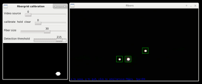
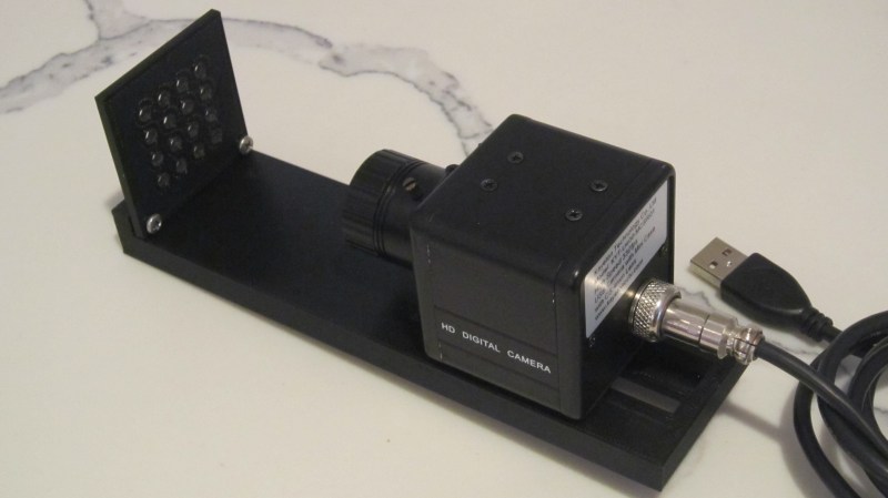
The idea is simple: make your sensors from light gates using fiber optics, feed the ends of the plastic fibers into a grid, then film the grid with a camera. After calibrating the software, built with OpenCV, you can “sample” the sensors through a neat abstraction layer. This approach is easier and cheaper than you might think and makes it very easy to add new sensors.
Naturally, it’s not fantastic for sample rates, unless you want to splash out on a fancy high-framerate camera, and even then you likely have to rely on an OS being able to process the frames in time. It’s also not very compact, but fortunately you can connect quite a few sensors to one camera – up to 216 in [rand3289]’s prototype.
There are many novel uses for this kind of setup, for example, rotation sensors made with polarising filters. We’ve even written about optical flex sensors before.


I had this idea years ago, but I wanted to make a touch screen by lining the edges of a display with fibers (half emitting light, the other half with their other ends arranged in a grid with a camera)
Trust an image recognition algorithm to do your basic sensing for possibly safety critical* conditions like limit switches? Really? This is a job for multiplexers, shift registers, GPIO expanders or slave microcontroller arrays (on SPI or I2C), keep it electrical to minimise energy losses caused by converting to light and back. Keep it dumb and simple to avoid the risk of the image processing code making a mistake, and because it is so much faster for an electronic device to just check if a GPIO is high or low (or exchange a few bits and/or bytes of digital logic) than to run all the fancy software needed to monitor and interprt a camera feed. Furthermore this thing is bulky, a litle stripboard or custom PCB for some logic chips would sit easily within the same space as a pi zero or arduino, this camera and frame rig would take up space, and maybe weight, which plenty of robot types can’t afford to spare. Oh and digital logic chips cost pennies, most cameras are going to be atleast £10.
*Sometimes not a person’s safety but not having your motor burn itself out or rip apart a gearbox while pressing a limited traverse component against the end of its run sounds important to me
“Image recognition” is only done once during device calibration. You can even do it manually without algorithms! Once the locations of the fibers are determined, data collection is done by a a few lines of code that sum up adjacent pixels.
This device is primarily for robotics. You can have 500 analog sensors running off a $10 web cam! How much is that going to cost you if you do it with electronics? Plus you can 3D print all your sensors or make it with glue and cardboard :)
Here is something I made in a couple of hours: https://hackaday.io/project/172309-3d-printed-joystick
Love this idea. If this could be proven to be long term durable it would be a great addition to an industrial control system in place of expensive go/no-go prox switches.
Neat idea. Next level: skip the fiber and just point the camera at the limit switches. :-)
As an extra note to my prior comment:
On further looking at the project logs I can see one circumstance where this could be useful, if you’ve got an environment which, for some reason, you daren’t insert anything electrical into then the optic fibres give a good standoff to get certain data out from the environment (though if the environment isn’t already naturally lit you’d have to send electrical current in to provide some light via LEDs). And the suggestion of using crossed polarisers on the end of a fibre to measure roation between them was pretty cool. Still it would seem easier to route each fibre to a phototransistor and ADC system than to aim them at a camera, would enable projects with just a small microcontrolelr rather than needing a full computer with an OS from which to run image reading code.
While I am on your side with all the concerns and this neither being a simple nor cheap solution (compared to single boolean reads on a GPIO) if you know what you want to have, but I think in the prototyping phase (for non critical switches) this might be quite neat, as you can easily add more triggers as it seems without worrying to much about where to connect them (free IOs, adding multiplexers, etc)
Could also sample other state of data if you use color wheels on one end for stuff.
Or… use a photodiode and just pulse each light individually, checking the state of the diode in sequence with the light activation. Better yet (but more complex from a programming standpoint), pulse each light at carefully selected frequencies and use some Fast Fourier Transform magic to tease out which ones are blocked and which are not.
To clarify, the would keep the fiber, but ditch the camera. And possibly allow faster response rates.
But pulsing each light individually requires the many IO’s which we’re trying to avoid in the first place. Unless you drive them from a counter chip/demuxer or something like that, and can infer which one was lit with perhaps just a single sync input and a HW clock.
Hmm… good point :)
I like the idea of using a counter chip, though.
In fact, with that kind of arrangement, you could just do this without optical fibers, as long as you’re using optical limit switches. Just connect all the outputs together open-collector style. Since only one LED is lit at a time, the combined output will tell you the state of the lit sensor.
Don’t even need a lens or grid, just bundle the fibres and glue it to the camera CCD-chip?
Optical strain gages do exist, but just looking at there connectors I guess there price range is unpractical.
What about using photodiodes and shift-registers? A bag full of them is cheaper than this camera.
You could chain a lot of shift-registers and read lots of sensors in sequence…
Is it really though? A good-enough camera can be had for $5-15. With bags of components, you have to do a lot of assembly of a board, along with more thoughtful planning about what your shift registers are doing. With this, you connect each sensor to coordinate and then poll for light at that place–done!
This is, without doubt, one of the silliest things I’ve seen submitted for a HD prize… It isn’t hard to get a chip with 16 inputs and put switches on them instead of doing this over complicated mess…
Who needs a computer when I can write on paper? :) Unless I am not thinking of a good use case… Oh, wait a minute… It says it’s a framework for robotics. Hmm… what if limited progress in robotics and AI is due to low sensor counts in current systems and increasing the sensor counts will revolutionize robotics? Wait a minute! A single FiberGrid camera can simultaneously read values from HUNDREDS of “analog” sensors. Many more than the number of ADC channels in any MCU! Eliminating the need to communicate among multiple MCUs. All that for under $100? No band or low pass filters as you would need for some ADC channels. No debounce circuits for interrupt triggering pins. No scheduling (waiting) for ADC completion in firmware. Read-modify-write problem will not haunt your in your sleep. No back EMF to deal with. No worrying about induced currents. Schmitt trigger is gone from your vocabulary. You no longer care about TTL and CMOS logic difference. Floating open collector what? Pull up pull down that reference voltage resistor ladder no more! Time the discharge of a cap through a pot on a digital pin never again… No more explaining all of the above to ten year olds in STEM, just give them a glue gun and let them make stuff, that kinda changes things…
The more I think about it, the more elegant it is. Bravo!
funny, many comments about the overkill of this system. Although I have to admit that from a technological point of view this is sort of overkill, i DO like the appeal/promise of the design concept.
Actually this is all about “out of the box” thinking, you can compare it to the 555 vs arduino blinking LED.
Sometimes you need to look to the end result and the efforts it took to get there and the efforts it takes to get there again and again and what it would cost to install, run and maintain. But also the skills it takes to make, run and maintain. This solution simply shifts many of those points to a different level.
I guess we all remember when cars were simple boxes with wooden wheels and a horse in front of it. Then someone thought it was a good idea to put a very complicated an noisy motor in it, blowing nasty fumes… but the whole thing didn’t go any faster then a horse (at first). So, what is easier the strapping a horse to a car and riding it?
Keep thinking out of the box…
I agree, and what is a camera except a grid of photosensors. Say you need hundreds or more, then look at the bags of chips. What if the project already has a computer? Then this would be a very easy solution, and a compact way to bundle a lot of sensors.