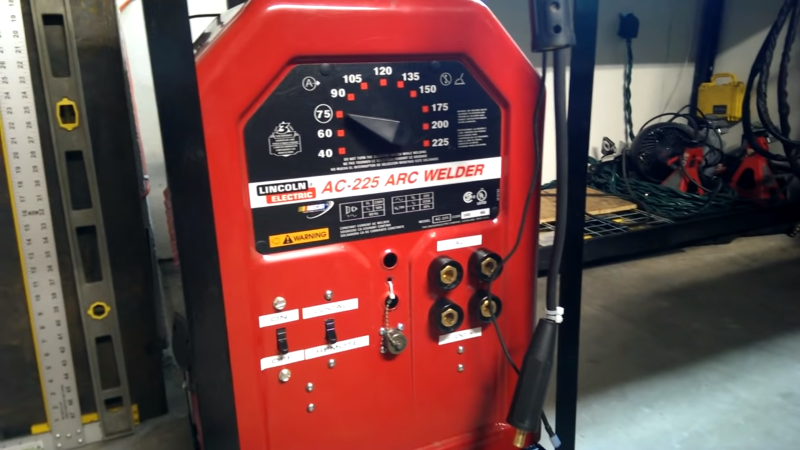
State-of-the-art welding machines aren’t cheap, and for good reason: pushing around that much current in a controlled way and doing it over an entire workday takes some heavy-duty parts. There are bargains to be found, though, especially in the most basic of machines: AC stick welders. The familiar and aptly named “tombstone” welders can do the business, and they’re a great tool to learn how to lay a bead.
Tombstones are not without their drawbacks, though, and while others might buy a different welder when bumping up against those limits, [Greg Hildstrom] decided to hack his AC stick welder into an AC/DC welder with TIG. He details the panoply of mods he made to the welder, from a new 50 A cordset made from three extension cords where all three 12 gauge wires in each cord are connected together to make much larger effective conductors, to adding rectifiers and a choke made from the frame of a microwave oven transformer to produce DC output at the full 225 A rating. By the end of the project the tombstone was chock full of hacks, including a homemade foot pedal for voltage control, new industry-standard connectors for everything, and with the help of a vintage Lincoln “Hi-Freq” controller, support for TIG, or tungsten inert gas welding. His blog post shows some of the many test beads he’s put down with the machine, and the video playlist linked below shows highlights of the build.
This isn’t [Greg]’s first foray into the world of hot metal. A few years back we covered his electric arc furnace build, powered by another, more capable welder.
https://www.youtube.com/playlist?list=PLlYTxvu80_kHRLCmdM3Wsly3nt6ea7aKJ
Thanks to [James Analytic] for the tip.


I have a tombstone AC welder too,
I’ve been thinking of what I need to do to make it AC/DC.
But that project is on “indefinite hold” as we needed its circuit breaker to supply the PTAC unit in our 3 season porch.
I’m doubtful of his using bridge rectifiers in parallel,
that seems to go against “most” of what I’ve learned.
Any comments?
It can work if they are nearly identical, but is risky since one will carry more current than the other(s). I might be willing to use three to carry 2x the rating of one.
If you look around on the web and Youtube, there are some other higher current rating single rectifiers being used that cost from $30 to $50… though his hack has to be the most cost effective. I just ordered four for under $3 for a motor controller project the Aussie Shed used since I wanted to study that cheap design. Then read about this and am like… neat… I have four of those already (though really need a fifth or sixth I’m thinking to overrate. Left wondering how in spec each are compared to each other?
Here’s what I wrote up regarding what’s on my mind so far with the last comment having the links to the other videos (I think at least the first one using the single rectifier method and I liked his tear down view too since I haven’t seen in years):
https://www.facebook.com/james.analytic/posts/3320575484670897
I’ll try to document when I open mine up when I get to it.
I’m curious how the Arc Pig is operating in detail. Anyone with any ideas?
in the absence of other series resistance, whichever one gets hotter will get the most current due to the negative tempco of forward drop in silicon, and therefore you have a potential runaway situation. Putting them all on the same heatsink is helfpul, but often not enough as die temperature isn’t the same as the heatsink. A little series resistance can help if it’s per-bridge, allowing better current sharing. Some is inevitable in the wiring itself (particularly at these current levels) sometimes leading to people saying “no series R is needed” – they forget that even though it isn’t on a schematic, a parasitic impedance can exist.
Thanks [Douglas] and [Bill],
I perused Amazon and saw several diodes and bridges that could handle >50 amps and PIVs of >= 300 volts, for <$100. If those specs will do, I'd rather go with one of those instead.
As mine has a duty cycle of (IIRC) 20%, I am also considering adding a 120V fan inside the case, as it didn't come with one. But, I probably wouldn't exceed the duty cycle anyway.
"What do you want on your tombstone?"
B^)
If you’re going to spend that kind of money though, you can just buy a welder with the features you’re after.
[ivan256]
I bought the tombstone welder 32 years ago at auction for $20, it was probably 20-30 years old at the time.
I also own a Hobart MIG and flux 120V welder I bought 6 years ago at Sears for $47.
(new, with cart and chipping hammer)
Converting the tombstone (20th Century Corp.) to DC, is probably cheaper than buying another welder. It looks similar to this one.
https://talk.newagtalk.com/forums/thread-view.asp?tid=215525&DisplayType=flat&setCookie=1
dona nobis pacem
I almost purchased one of those 20th Century Corp. ones for $50 and am still feeling I paid more than I needed for the Lincoln AC225/DC125 I invested in. Then again… I only need to do the DC hack if I want to have DC 225A.
I only paid $20 for the Lincoln AC225 I used to have. I’m thinking I might still buy that $50 one just in case.
I’m going tomorrow to pick up the 20th Century Corp. for $50. Will be a good rescue and make a good project. https://drive.google.com/file/d/1vDFyRc_Q5lR5ZDAYEBPUjVnk7O8_oEt2/view?usp=sharing
[jafinch78]
I see they’ve already painted it for you!
B^)
I had some “Burgundy” colo[u]red spray paint, so I cleaned, sanded, and masked off about 1/2 of mine and sprayed.
It looks “half” new!
B^)
Good luck with your purchase!
Thanks, [Ren]!
Thanks [Ren], good logic I hope!
I just got back with the 20th Century Corp. and it’s heavier than the Lincoln Electric AC225/DC125. Wondering if more steel or copper?
Reads like there is controversy regarding quality of performance over the years made of the buzz boxes based on having more copper or not as the theory.
Just feeling this one (haven’t unloaded yet since kind of late), feels like has a variac control and not a transformer with tapped leads and a multiple switch. Exciting actually just regarding that component alone!
Came with two welding helmets and one is a sensor autoshade one which is a bonus if works OK and also a matching color set of gauntlets. I’m thinking the design of this one might be better… though will be interesting to try to perform a side by side comparison being the 20th Century Corp. will have the upgrade to DC performed. I’ll focus just on repairing the switch on the Lincoln Electric for now.
When I open up, I’ll take some photos and post at least on my FB since I haven’t found much for detail regarding teardown online.
I didn’t realize the beast has a 310A cutting line out.
https://uploads.tapatalk-cdn.com/20180414/6b231c747b9028693d2d4fe9b99c686a.jpg
Makes me wonder about a plasma cutting torch hack?
This is going to be an interesting project for sure and gets to cut in line!
If you use one choke coil on negative side will be more better
300A single phase bridge rectifier is only 25 bucks on eBay. Wind a reactor with a MOT and some 4 gauge wire and you’re good to go
“Wind a reactor with a MOT and some 4 gauge wire and you’re good to go”
I’m assuming you don’t mean molecular orbital theory (MOT) and you mean Microwave Oven Transformer (MOT)?
I thought at first Metal Oxide Transistor (MOT… then no that’s Metal Oxide Field Effect Transistor MOSFET)… then thought about it some more after finding the King of Random MOT Jacobs Ladder.
Reads like an extra MOT would improve [Greg Hildstrom]’s design for AC stick welding which I never even heard of until reading this. I have seen the MIG non-spool aluminum hack not using a spool gun:
https://www.youtube.com/watch?v=CzcyA6Z-8dk
On another note, I was looking at some pulse and waveform methods and am wondering the best way to most cost effectively reliably add those options for a TIG Welder square wave design since thinking might be able to build a TIG Welder add on as a rewarding project vs buy one and improve on the Lincoln buzz box DIY hacked together design.
I found these two references though looks like is a pricey endeavor:
High Voltage Trigger and TIG Welder:
http://www.imajeenyus.com/electronics/20110511_high-voltage_trigger/index.shtml http://www.imajeenyus.com/electronics/20110425_tig_welder_mirror/TIG_Welder.html
TIG Welder and Power Control:
http://www.thompdale.com/tig_controller/tig.htm
http://www.thompdale.com/footpedal/footpedal.htm
Then this IGBT way:
https://wenneskrachgibtgehnwirindiewueste.wordpress.com/2017/05/16/arduino-powered-tig-acdc/
Thinking would need to wind some MOT’s maybe or make better performing inductors to level out an SCR’s end of the current waveform along with a tuneable capacitor that would be geared, or electronically controlled, to keep the potential phase in line when changing frequency so can tune from 20Hz to 400Hz.
https://www.allaboutcircuits.com/textbook/semiconductors/chpt-7/silicon-controlled-rectifier-scr/
Any ideas for a square wave design for a hacked TIG Welder?
I’m still wondering what the Arc Pig is exactly.
I’m still not sure how to offset the DC square wave back to alternating in a high current/potential way since IC’s aren’t designed for high power… though maybe just making an AC square wave is easier if chopping the positive and negative with two SCR’s and filtering. Ideas?
Another control circuit with the schematic location noted in the description:
https://www.youtube.com/watch?v=jkM4LWm3GyY
Found this neat design for an AC welding circuit design. Super simple and thought worth documenting, if not creating an article of er own:
https://www.youtube.com/watch?v=5V7aUaB0A1A
After learning a little more regarding electronics, albeit just coming inside to refresh the indoor season more focus on since hardly over the outdoor projects season use, I thought the following. Is this correct thinking:
“I’ve assumed that the waveform was rectified to a pulse DC waveform from the AC 50/60hz input then smoothed to be CV and/or CC. Then, based on a controller of some sort to recreate the waveform like the gentleman does with the SCR and some circuit, instead of using the series of zener diodes switched, the for example MCU design would use an H-Bridge to switch (invert) between a DCEP and DCEN so that the desired waveform was recreated without that slight lag time of 0 volts and any desired frequency (based on the components used) could be switched. So you could based on the MCU program, create say 20 to 120Hz square waves or sawtooth or sine waves with which ever balance you wanted at for DCEP and DCEN. Where the alternating DC square wave would be the easiest to program waveform. “
Was thinking about a simpler instead of zero crossing clipping design, the typical negative clipped in an adjustable way design, specifically the series-negative clipper with negative bias circuit design.
This simulation linked below seems about right for the theory and with a 70% electrode positive and 30% electrode negative balance:
https://tinyurl.com/2ksflnqy
However, not sure how to handle practically and cost effectively DIY the resistors in the clipping design other than like oven stove top or quartz tube elements sections and then dealing with a lot of heat and losses. Maybe making carefully the very large components way overrated. Say a 120VAC 15A input wouldn’t be as bad as going higher in current. The diode that can handle the current would be readily on the market most likely, though I have no idea regarding the potentiometer for such high current other than maybe a toaster oven control or maybe some sort of breaking rheostat?
Kind of pushing the theory vs practicality, though is an interesting exercise. Is interesting thinking about how to practically cost effective DIY the variable resistor as well… though the losses would be significant and make not a very energy efficient design. The
I definitely see why the way more efficient solid state SCR’s or IGBT’s in an H-Bridge design are used like in the Miller Syncrowave designs and others. Less losses in the circuit and less zero voltage time, so don’t have to worry about using HF throughout the welding time so the arc isn’t lost. Plus you can make a pulsed DC waveform like a square wave with the frequency control you want like say 20-250Hz and also make other waveforms like sawtooth or whatever your heart desires.
Here’s a more current link regarding the Modified Tombstone welder hacks:
http://nathandarnell.com/ac-225-welder-amperage-control-with-scrs
Here’s a simpler DIY fine tuning controller design and complete homebrew MOT and other salvaged for the most part hacked together DIY $20 welder:
https://youtu.be/c_q_cYIgixI
Dan did you train distributor sales people at one time?
Was with Steve and a Mahoney advanced Mig tug in mid 80’s
I abuse automotive alternator trios on experimental rigs. Not just welding. Helps to know local rebuild shop that rips em out and replace regardless of operating condition.
Cool thing i’m not the only one using a few paraller diode bridges. I was concern about charge balance, but they seem to work fine.
They’re the cheapest option in price/current.
I’m missing the by-pass capacitor for the high voltage, i might try a Varistor in paraller with a few capacitors and hope is enought
Just get a full wave bridge rectifier from Ebay, I got one that is 150 amp for $25.00 and my 1950’s Hammet 100% duty cycle welder is reverse polarity DC. capable now.
Let’s see. I can get a 25′ 12 ga extension cord at HF for $19.99, and you need two of them so that is $40 and it is not really welding cable and it only works out to 7awg, and given you are cutting the ends off, you also negate any possible future use as an extension cord. That may have been a plus for using them this way. You can get 50′ of real 4 gauge welding cable off of eBay for $51. That is $11 more. Truthfully, that sounds like a much nicer way to go, though if you did keep the extension cord ends, that would be a few points in your direction. It may be useful to be able to abscond an extension cord or two if you are not welding, and it also may be handy to be able to extend one or both of the welding leads with stuff you may have kicking around.
I have an old tombstone buzzbox, and I cocnsider myself poor, but if I were to look into changing it, I would have my eye on one of the new inverter powered units. They are just so much nicer. Being able to run it off of 110 or 220 is the big one.
About the only thing I can say really in favor of the old beasts is if you hunt around long enough, you can probably find one for free, and as long as you don’t try changing the amperage on the thing while you are welding, they are hard to kill.
Seem pertinent to reference regarding transformers: https://www.youtube.com/watch?v=2cxcP5lY7K4
I have this feeling electroboom needs a video referenced regarding a full bridge rectifier!!! :-)
Thinking I want to design in a circuit for battery charging and/or vehicle starting while at it?
I have one of these that I bought brand new over 40 years ago. Toyed with the idea of adding DC to it as a friend did to his over 30 years ago. Never go to it. I have a mig and gas powered welder and the tomb stone sits there unused. This might cause me to turn it into a TIG machine. Well done. And Thanks.
I’ve got a question. It comes from something I’ve been tripping over and meaning to tear apart for the nice little plastic case it comes in… Has anyone ever thought, for the purpose of welding 18650s together for battery construction, of using a thermocouple attachment unit like this one http://viaducttrading.com/products/mini-weld-thermocouple-attachment-unit. I also have a slightly bigger thermocouple and stud welder that seems like it would be just perfect to spot weld 18650’s ..
Some great videos probably worthy of their own article… though for now:
https://www.youtube.com/watch?v=k5684mQJQRU (How Welding Transformers Work… background video mentioned in the next linked)
https://www.youtube.com/watch?v=yzOr1bnArVI (Welder Experiments! DIY Upgrades for Cheap Stick Welders!)
Ive welded with the tombstone lincoln 225 for many years. Finally modified it to DC in about 2003 and used it since. It got wet while using it overnight just to keep 120V alive for another application and it melted the input winding. If you look at the Miller shunt type adjustment on the welders, they have an inductor and allso what appears to be an optical coupled triac for the suppression of either spatter or rf interference. Not sure which. But as an electronics engineer, I think and have experienced that my welds even with the tombstone were not where I liked them especially for the 7018 rod. I think that Miller has the better technology even after converting it to DC and would like to find the value of inductance needed to improve the tombstone’s welds. I think Millers development has produced a welder that produces better welds to reduce the spatter for their DC welders.