Here at Hackaday, we see all kinds of mechanical construction methods. Some are impressively solid and permanent, while others are obviously temporary in nature. The latter group is dominated by adhesives – sticky stuff like cyanoacrylate glue, Kapton tape, and the ever-popular hot glue. They’ve all got their uses in assembling enclosures or fixing components together mechanically, but surely they have no place in making solid electrical connections, right?
Maybe, maybe not. As [Tom Verbeure] relates, so-called Z-tape just might be an adhesive that can stand in for solder under certain circumstances. Trouble is, he couldn’t find the right conditions to make the tape work. Z-tape, more properly called “Electrically Conductive Adhesive Transfer Tape 9703”, derives its nickname from the fact that it’s electrically conductive, but only in the Z-axis. [Tom] learned about Z-tape in [Joe FitzPatrick]’s malicious hardware prototyping workshop at the 2019 Hackaday Superconference, and decided to put it to the test.
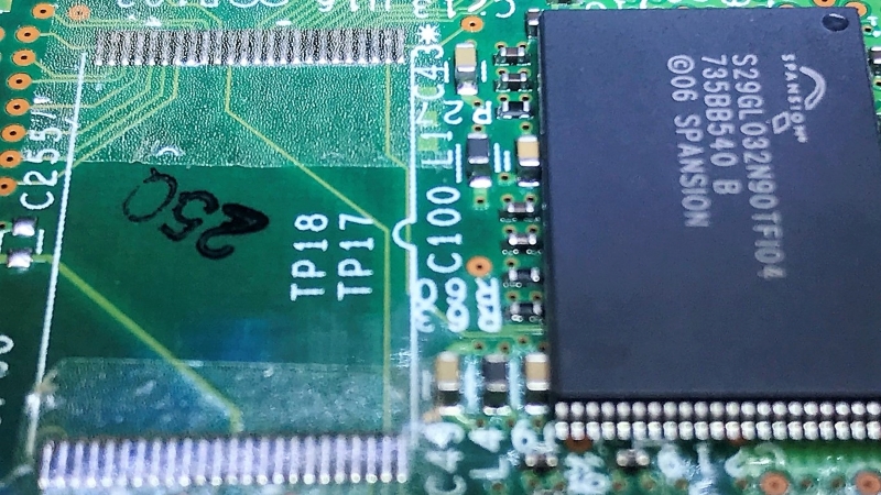
A card from a Cisco router served as a testbed thanks to an unpopulated chip footprint. The 0.5-mm pin spacing on the TSOP-48 chip was within spec for the Z-tape, but the area of each pin was 30 times smaller than the recommended minimum bonding area. While the chip was held down mechanically by the Z-tape, only five of the 48 pins were electrically connected to the pads. Emboldened by the partial success, [Tom] tried a 28-pin SOIC chip next. The larger pins and pads were still six times smaller than the minimum, and while more of the pins ended up connected by the tape, he was unable to make all 28 connections.
Reading the datasheet for the adhesive revealed that constant pressure from a clamp or clip might be necessary for reliable connections, which suggests that gluing down SMD chips is probably not the best application for the stuff. Still, we appreciate the effort, and the fine photomicrographs [Tom] made showing the particles within the Z-tape that make it work – at least in some applications.


A friend used the Z-tape to fix their HP 200LX screen. these have issue with the flex coming to the screen’s board being bonded by pressure from a foam pad.
Wonder if a blob of balsa cement in the middle there would have helped, that stuff shrinks and pulls gaps together a bit… trying to think of other adhesives like that.
Heh, seems everyone spent the last couple of decades trying to stop their adhesives shrinking. Best guess so far is bone generic cheapo epoxy and cure at higher temps… gut feeling is several small dots of it would do better than one blob. Idea being to just put the Z tape on the contacts and use shrinkage of adhesive to try to pull the component down tight on them.
Sounds like a sticky, lower-density zebra strip…
What is a zebra strip?
Ah, these rubber connectors of LCDs.
I assumed that was where the Z came from until I read the “Z direction” thing. Still, it seems more likely it is a Zebra connector in a tape form, thus “Z-Tape”.
Does anyone fancy trying this with a BGA? That feels like it might stand some chance of working.
The solder contact area for a BGA is even smaller than for a TSOP-48, especially because the contacts are balls. There’s no flat surface to be found.
So I expect it to do even worse.
There is that. I was imagining that the balls might sink in to the tape surface.
One might consider lapping the balls flat, to their maximum diameter point.
“One might consider lapping the balls”
Well, if you’re offering..
Or wick the balls off.
This is HaD not Grinder.
That would be a great challenge because of the surface tension, the balls would just pop back to round. If you’ve ever reballed a bga with solder paste, a stencil, and a heat gun, you’ll already know what a PITA it is to do it right. Much worse to do it wrong.
good luck positioning a 0.4mm BGA without solder surface tension helping out
That reminds me on something:
I have an old Texas Instruments TI Voyage 200 which I attempted to repair some time ago. Unfortunately, I was not able to connect the display (old LCD with rubber connections) properly and now the screen is showing stripes.
Did somebody repair such LCD screens already and could give me some tipps how to do it? Would this z-tape help to connect the LCD screen to the motherboard via the rubber connector again?
How am I able to repair bad connections of a LCD screen with rubber connectors in the first place?
In my (admittedly limited) experience with LCDs and zebra strips (that’s one of the names for the conductive rubber connector things), the usual cause of a faulty connection is lack of sufficient pressure between the LCD, the rubber, and the PCB – I’ve managed to repair some LCDs with dead segments by shimming whatever mounting mechanism holds the LCD-rubber-PCB sandwich together with a sheet or two of regular paper – It doesn’t take much. Gently cleaning the rubber, LCD and PCB contacts with some isopropyl alcohol is also a good idea.
Ah yeah, done similar, for shims I use plastic though, cut out of a margarine tub lid, or side of a PET bottle, or for thinner ones, the flat bits of bubble packaging.
Thanks, I will try this.
So the guy tried two chips that were WAY below the spec for pad footprint and it didn’t work. Is anyone surprised?
I agree, which makes me wonder why did hackaday even bother posting it. Must be getting desperate for material
I’m “that guy”. I can’t answer the question why Hackaday thought it was worthy of publishing, I can provide some perspective:
First of all, doing things this would never have been a good idea. It took less time to solder the chip than to try one experiment.
So why do it then?
Just to see if something works. It was fun, only took a couple of hours to do, and I found the whole concept interesting.
On my second try, I got pretty close. One half of the chip was fine. This tells me that, with practice and better procedure, it could actually work. The density of the z particles is such that there will always be multiple ones under the same solder pad. Also, on a PCB without solder (e.g. a milled PCB), results would definitely have been better due to flatness of the surface. Someone on twitter who knows this kind of product offered suggestions on how improve yield.
Finally, one simple goal of doing this was to observe z particles close up. there are multiple pictures on the web already, but none of them had a sense of scale: I had no idea how big the particles were and how dense they were populated. Just like some people want to know how a rocket engine works even if they’ll never successfully build one, I wanted to know what made z-tape tick. I think the product is a fascinating piece of engineering.
I had never heard of z-tape before last weekend, and thought it was incredibly cool when Joe introduced it to us. If the writeup here has the same effect for who knows how many others, I consider that mission accomplished.
“Also, on a PCB without solder (e.g. a milled PCB),”
Or ENIG (as is often used for SMT PCBs). In fact the picture looks like it might be an ENIG board, but with solder exactly where you don’t want it.
Thanks, one can learn much more from something that did not work, than a “success”.
I may try and test the spec myself on a small chip
Cheers
“Thought it might work, tried it, it didn’t” is totally useful for the whole community.
Disregard the naysayers.
Thanks.
I’ve used z-tape before. It works wonders when you use it in spec. It is a bit like Saran Wrap in that it sticks to itself very easily and you can end up wasting quite a bit if not cautious.
Do NOT try to use it on ribbon cables in a plasma TV. There’s not enough isolation between the conductive particles. The sparks look pretty as they dance between the conductors of the ribbon, but will ruin the scan ICs.
Pondering mechanical hold downs, I just thought of epoxying short flat head bolts either side, and using a bar clamp, or spare heatsink, may as well make it twice as useful, and nuts to draw it down. Trying to find a bare bit of board surface would be most ideal, since traces can pull up easy. Anyway, just dawned on me that this could be a bandaid for troublesome early lead free era BGAs, that haven’t improved much with simple flux reflow attempts and the kit isn’t worth sending it off to be reballed or “professionally” repaired (Though that’s a bit of a dice roll whether they’ll actually do a full reball and flow or try the same crap you did)
I was always under the impression that Z-tape was good for low-current signals like in LCD panels, but not so great for chip Vcc/Gnd lines. I have a hunch that soldering flywires to the power leads might let the rest of the chip work with the tape.
You’re definitely right about Z-tape only being good for low-current (and low voltage! see comment above!) signals.
I measured the resistance through the connections that worked, and it showed up as 0.3Ohm, but that’s with a huge error margin of a semi-decent multimeter.
But flywires wouldn’t have saved me: when it failed, there simply wasn’t a connection at all.
That 3M Z-tape is actually quite neat stuff, I was surprised by how low the resistance was, but maybe a bit too high for the power-lines of a chip. It worked for re-attaching a cable to a thermostat LCD display. Applying the thin tape without wrinkles is a challenge and in my case there where issue in the cable itself.
Its also good for reattaching ground planes on damaged phone LCD/OLED screens.
Also, don’t these things need mild heat AND pressure to set properly?
I worked with lcd suppliers who use a similar tape to connect thousands of PCB conductors to flex circuits and those flex circuits to the glass. Their tape is set with a hot roller which melts the adhesive and compresses the balls. The adhesive hardens when cooling. I wonder if the heat and pressure is required for this z-tape?
I got the vibe that the product is getting a bad rap here when the person who used it is clearly not using it as it was intended to be used. This is just sloppy journalism IMHO. To be fair you really should have had someone try the product the way it was intended to be used. I have a friend who is famous for using products way outside of their specs and than complaining when they do not perform well.
I don’t see any comments here that are dismissing the product itself?
This website is called Hackaday: one that publishes hacks. My experiment should be seen in that context.
Nowhere do I advocate in favor of using the product that way I tried it. Was “…It’s not that you should …” in the title not enough of a hint? Was I not clear enough with “It was never intended to be used as an alternative to soldering chips onto a board and thus it doesn’t work in that capacity.” ?
Nor do I claim anywhere that the product is bad at what it was designed to do. Did you miss the conclusion that “Z-tape is a pretty cool product.” ?
Nah. Is very cool product but for that pin spacing wasnt likely to work. 0.4mm suggested minimum gap and works best with mechanical pressure applied IMo. Assumption that traces run near are also far enough away as to not short to. Should work with other wider spaced chip outlines but still think need mechanical pressure. Works real well LCD zebra shim for them ol shrunked up strips. That and shit aint that cheap and loves to stick to itself like good roll of duct tape.