Here at Hackaday, we see all kinds of mechanical construction methods. Some are impressively solid and permanent, while others are obviously temporary in nature. The latter group is dominated by adhesives – sticky stuff like cyanoacrylate glue, Kapton tape, and the ever-popular hot glue. They’ve all got their uses in assembling enclosures or fixing components together mechanically, but surely they have no place in making solid electrical connections, right?
Maybe, maybe not. As [Tom Verbeure] relates, so-called Z-tape just might be an adhesive that can stand in for solder under certain circumstances. Trouble is, he couldn’t find the right conditions to make the tape work. Z-tape, more properly called “Electrically Conductive Adhesive Transfer Tape 9703”, derives its nickname from the fact that it’s electrically conductive, but only in the Z-axis. [Tom] learned about Z-tape in [Joe FitzPatrick]’s malicious hardware prototyping workshop at the 2019 Hackaday Superconference, and decided to put it to the test.
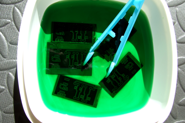
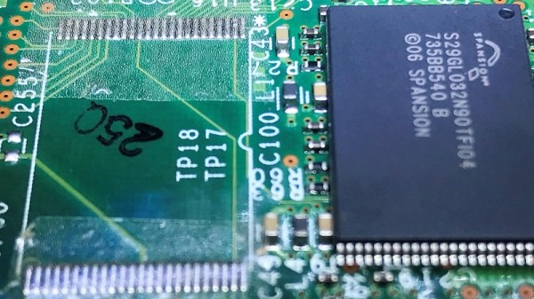
A card from a Cisco router served as a testbed thanks to an unpopulated chip footprint. The 0.5-mm pin spacing on the TSOP-48 chip was within spec for the Z-tape, but the area of each pin was 30 times smaller than the recommended minimum bonding area. While the chip was held down mechanically by the Z-tape, only five of the 48 pins were electrically connected to the pads. Emboldened by the partial success, [Tom] tried a 28-pin SOIC chip next. The larger pins and pads were still six times smaller than the minimum, and while more of the pins ended up connected by the tape, he was unable to make all 28 connections.
Reading the datasheet for the adhesive revealed that constant pressure from a clamp or clip might be necessary for reliable connections, which suggests that gluing down SMD chips is probably not the best application for the stuff. Still, we appreciate the effort, and the fine photomicrographs [Tom] made showing the particles within the Z-tape that make it work – at least in some applications.