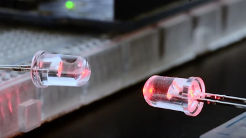
We’re all used to the humble LED as a ubiquitous source of light, but how many of us are aware that these components can also be used as photodiodes? It’s something [Giovanni Blu Mitolo] takes us through as he demonstrates a simple data link using just a pair of LEDs and a couple of Arduinos. It’s a showing off his PJON networking layer, and while you’d need a bit more than a couple of LEDs on breadboards for a real-world application, we still think it’s a neat demonstration.
PJON itself is very much worth a look, being an implementation of a robust and error-tolerant network for Arduinos and other small microcontroller platforms. It has a variety of communication strategies for various different media, and as this LED demonstration shows, its strength is that it’s capable of working through media that other networks would balk at. Whether it’s controlling home automation through metal heating ducts or providing an alternative to LoRa at 433 MHz, it’s definitely worth a second look. We’ve mentioned it before, but remain surprised that we haven’t seen it more often since. Take a look, the video is below the break.


Funny, I used this principle 6 years ago:
https://github.com/ChrisMicro/LedDataTransmission
Ciao Chris, thank for the link, I will look into it.
To be precise, I implemented the first prototype of the LED data link 9 years ago, here is the video demonstration still present on youtube: https://www.youtube.com/watch?v=-Ul2j6ixbmE
http://www.merl.com/publications/docs/TR2003-35.pdf
Thanks for posting the link to our paper. Here’s the demo video from 2002:
https://youtu.be/O3Pf4TZ_vOE
I built a laser receiver using an LED back in 1977 based on a Mimms article. So the trick goes back at least 40 years! Our contribution was realizing that you could do this with a standard microcontroller without adding ANY additional parts.
At MERL, we had a demo going doing LED com across a large room – no lens or light guides. And no adc. That one used some clever tricks to precharge the LED to close to threshold using an additional resistor. This let us do really fast measurements, even in low light.
Over the last two years, I ran workshops at SIGGRAPH that covered some of this, along with my hot LED anemometer which graced these pages a couple of years ago…
I have a few more LED tricks to prove out. So stay tuned. With any luck people will still be rediscovering these in the 2060’s… ;)
Ciao Paul compliments for your publication and your research. Your work was an inspiration. I would be happy to know your feedback, if you can give a try to AnalogSampling.
>Ciao Chris, thank for the link, I will look into it.
Well, don’t look to deep, the code is a little bit messy. Today I would make an Arduino library out of it.
Originally I used only digital pins for LED communication. But in the later versions I used the ADC. With this I could achieve better noise light suppression. If I remember right, the fastest speed was 1kB/s ( hardware LED+220Ohm ).
An easy to use Arduino library would be of great use. I think it should be Arduino-stream compatible
https://www.arduino.cc/reference/en/language/functions/communication/stream/
Do you have such an example?
AnalogSampling reaches 1.528kB/s or 12658Bd at mode 5 see docs here: https://github.com/gioblu/PJON/tree/master/src/strategies/AnalogSampling#performance
Although I will soon release mode 6 which will be even faster.
Sadly my comments of 2:37AM are still waiting moderation, while your comment instead is being published already and that to be seems quite strange. I will not duplicate information and wait for approval there you will find the answers you ask.
Yes, although it is not stream compatible, AnalogSampling is an option, that reaches 1.528kB/s or 12658Bd at mode 5 see docs here: https://github.com/gioblu/PJON/tree/master/src/strategies/AnalogSampling#performance
Although I will soon release mode 6 which will be even faster.
Matthias Koch published his LED Comm many years a go – together with necrisp Forth Software – you find it at http://mecrisp.sourceforge.net/ledcomm.htm
Ciao, what you present uses the LED in reverse-bias to make the measurement, or what was showed in the Arduino LED sensor example published around 2010. That requires the use of 2 digital IO pins and it is a less efficient way to obtain the same result. I do use the LED in photovoltaic mode, that requires just 1 IO pin and a circuit that is much more similar to what is needed to use the LED as an emitter. Furthermore, using photovoltaic mode you can obtain a higher bandwidth and range. Happy tinkering.
“using photovoltaic mode you can obtain a higher bandwidth”
Have you tested this?
From memory the input impedance for atmegas is about 30 meg.
Even in photovoltaic mode the LED will self excite resulting in a voltage stored in the junction parasitic capacitance.
You’re draining this off with a 300k resistor and that is improving the bandwidth.
Could the same be done in reverse bias mode to achieve improved bandwidth perhaps?
One potential usage case for reverse bias that I haven’t tested is to use the led to replace a button input.
The presence of a finger over the LED may alter the discharge time. I suspect this may not work well as the difference may not be easily detected due to the high level of self excitation.
Perhaps it would be better to use closely adjacent LEDs as separate emitter and detector in PV mode.
This might even be useful for LED matrixes as both an output and input device.
Due the the relatively low incidence angle of LEDs the proximity and diffusion would play a strong role.
Yes I have tested both distance sensors and data transceivers based on LEDs in both reverse-bias and photovoltaic mode. For distance sensing / reflectometry, if you don’t need quick sample rates, reverse-bias may give a higher resolution and more range, although for data transmission, the discharge time in reverse-bias is the bottleneck.
I have wondered how well this would work with 4 lead RGB diodes
Ciao, what you present uses the LED in reverse-bias to make the measurement, or what was showed in the Arduino LED sensor example published around 2010. That requires the use of 2 digital IO pins and it is a less efficient way to obtain the same result. I do use the LED in photovoltaic mode, that requires just 1 IO pin and a circuit that is much more similar to what is needed to use the LED as an emitter. Furthermore, using photovoltaic mode you can obtain a higher bandwidth and range. Happy tinkering.
For all who will further quote other approaches which use the LED as receiver in reverse-bias mode (when a photodiode is powered in reverse, will then discharge at a rate that depends on how much light hits it, and the higher is the amount of light, the quicker will discharge) is an indirect and less efficient way to obtain the same result if compared to what is shown in the video or the use of LEDs as photodiodes in photovoltaic mode. Why? See the LED as a solar panel, if you power a panel in reverse, and then disconnect it from the source, the voltage produced by the solar panel will fight against the one introduced by you, and so you could determine how much light the hits the panel, but that is stupid. It is better to just plug a tester to its poles and read the voltage that comes out of it.
That is one of the papers I have studied soon a decade ago that helped me to implement the software I am showcasing in the video. See my comments below to understand why the approach proposed is more efficient, less complex and more handy if compared with the reverse-bias measurement proposed by the paper you link.
“but how many of us are aware that these components can also be used as photodiodes?”
Hopefully most of us designing electrical circuits since it is basic knowledge.
Exactly most silicon diodes, transistors and ICs are at least somewhat photo sensitive. Or did people already forget the issue with raspberry pis where a camera flash would crash them cause of a regulator chip that was bare exposed silicon on the board?
Turns out a lot of MEMS microphones also have some sort of photovoltaic sensitivity, allowing an attacker to use pre-recorded audio to modulate the intensity of a laser pointed at devices like Google Home from a long distance or through a window (causing a deformation of the microphone diaphragm – I’m unsure how that works) to trick them into thinking they heard spoken audio when in fact nothing made any noise during the attack. You wouldn’t even need a very clean signal as most of these assistant devices are designed to cope with imperfect acoustics when commands are issued normally!
https://www.youtube.com/watch?v=iK2PtdQs77c
Ahhh… got it now… the intention is the product placing of the PJON book mentioned in the YT clip… :-Þ
Working full-time on open-source is economically hard, some financial support is required to be able to present free software to the world, the book is a way for users to do so if they wish. I hope this does not offend you or any other reader and I must underline that we have not paid Hackaday for this publication. Happy tinkering.
There is absolutely nothing wrong with getting some free advertising for your book. I hope you get many sales.
These crazy Hackaday kooks might even be using ads on this site to support themselves! Unheard of!
Some remarks:
@2:40 “Once you’ve found a pair of LED’s that perform well”. Indeed.
Some LED’s perform very badly in this department. The easiest way to test is to hook the LED up to a DMM and measure it’s output voltage, while experimenting with the amount of light it catches.
Some LED’s have only 10mV or even less output.
@ 2:45 He pulls resistors out of the paper tape for the breadboard. This is a very bad practice. Often glue sticks to the wire ends and this will get transfereded into your breadboard contacts, where more dirt sticks to the glue, which makes your breadboard unreliable in the long term.
Story about someone else’s project:
In some old low-power battery fed microcontroller project the output pins for the LED’s were switched to inputs when not in use to shave a few uA of the power consumption, which worked well in the laboratory. After deployment of the product and in bright sunlight the LED’s sometimes generated enough voltage to bring the uC inputs in the lineair region, which generated lots of leakage current and drained the batteries very prematurely. (Source: probably one of Jack Ganssle’s articles)
Thank you for the resistor glue tip, I will for sure avoid that in future.
About the story of the LED used as a small solar cell, with proper testing it would not have happened, and also nowadays exist LEDs rated for both reception and emission with detailed datasheets.
Most of such things are easy to test for, once you are aware it could be a problem.
However, in a circuit design with many components, a uC, firmware, etc it is very easy to miss some important detail of one of the components.
Do you have a link to a datasheet for a LED that is rated for both emission and reception?
I did a brief search for a datasheet of such a thing but I only find slightly related info (such as matched LED and phododiode pairs)
30 years ago, “Toys R Us” was selling a toy com set using optical signals. $20.00 or so.
A 30 second google shows commercial com rigs, https://www.lanshack.com/HOOTS-850-MM-talk-set-P6970.aspx
but the toy market seems devoid of type.
The idea is nice, but as an Italian myself I absolutely hate the pronunciation.
I have played with various types and colors of LEDs as photocells and had a decent amount of fun doing so. I used several different flashlights and even lasers to power them. I didn’t come up with any practical uses for them (I was just tinkering and having fun) but I do remember that high brightness red LEDs always seemed to give the highest output voltage for a given amount of incoming light.
I never tried it myself, but after typing the paragraph above I find myself wondering if one could use a joule-thief to make an LED light an LED. Might be fun to try.
1) with the correct component selections it seems like it could be done. 2) I have get to get around to playing with common anode/cathode RGB LEDs I want to see the differences between the junctions outputs when illuminated by different wavelength sources.
For all who will further quote other approaches which use the LED as receiver in reverse-bias mode (when a photodiode is powered in reverse, will then discharge at a rate that depends on how much light hits it, and the higher is the amount of light, the quicker will discharge), that is an indirect and less efficient way to obtain the same result if compared to what is shown in the video or the use of LEDs as photodiodes in photovoltaic mode. Why? See the LED as a solar panel, if you power a panel in reverse, and then disconnect it from the source, the voltage produced by the solar panel will fight against the one introduced by you, and so you could determine how much light the hits the panel, but that is stupid. It is better to just plug a tester to its poles and read the voltage that comes out of it :)
Back when we did the original LED Comm work, cheap micros did not have ADCs. So I think our solution was fairly elegant. Also, it used only the same parts as lighting the LED. Most versions used two I/O pins, but with the right voltage levels and right LED, you could also do a 1 pin version (which we also did).
A cool party trick is to connect two LEDs together, shine a bright light on one and watch the other very dimly light up. Yes, with the right LEDs and a very bright light source, that really dies work!
Thank you for your kind response, your paper was an inspiration.
Compliments for your eye-opening research.
wow 23 and half years ago I first learned about this from Forest M Mims.
This is one of those electronic trics that gets forgotten about because its so obscure.
I, too, learned it from Mims. It was very much a “Well, duh, of course. Why didn’t I think of that?” moment.
Then I looked more deeply into it. In short, LEDs make really, really crappy optical receivers. They’re inefficient, insensitive, noisy, and poorly characterized. Even re-using the one component as both a transmitter and receiver is tough to justify, as the overhead in other components outweighs the savings (for all but the most trivial application anyway).
When really good detectors can be had for pennies, it’s usually pretty dumb to consider using LEDs.
About the only time I’d consider an LED as a detector is if: a) I want to be sure the optical path is the same outbound and inbound — very useful in optically-coupled systems (lenses, fibers); or b) I want to take advantage of the wavelength specificity of the LED (e.g. blue LEDs are sensitive only to blue or shorter wavelengths), and don’t want to hassle with an optical filter. Forrest points out this useful property in one of his notes.
That was a key part of Forest Mims’ coronation ncept, using it with fibre optics.
Using an LED at each end meant it could transceive, a single strand of fibre optic and the direction depending on which LED was issuing light. That’s the importance I remember, not just some novelty or a general plea to use an LED as a receiver.
Ditto on Mims, but at the time I could never source the larger diameter plastic fiber he used. His notebook inspired something I later found useful as an improvised opto-isolator: simple LED+photo cell+”light tube” made of Cat5 insulation [or heat shrink]. Just your basic switching circuit where the photo cell was connected to the base of a transistor on the receiving end and the LED caused it to conduct.
https://cdn.sparkfun.com/assets/learn_tutorials/1/9/3/npn-switch-led.png
I’m sure a reverse biased LED could be used on the receiving end instead of the photo cell. As for bi-directional communication using LED pairs…no one has mentioned a pair of fibers. It goes without saying, but saying it anyway.
Wow, I had forgotten about the improvised optoisolator
Forrest M. Mims III wrote lots of articles and books on electronics, including optical communications using LEDs that goes back at least to the mid 70’s (that may be in a Popular Electronics archive). I worked at the now defunct electronics store BA (Burstein-Applebee) in KCMO back in the mid 70’s and would read his and other tech books while going to school to get my BSEE. Later, in the 90’s I think, he sued AT&T over patent infringement because they inadvertently tried to patent several of his prior ideas. Amazon has dozens of his books, but I could not find that really old one (the oldest I saw was CW 1987).
Siliconnections… I have a copy somewhere…
In my days of college, 3yrs ago, my friend used simple one LED as a touch sensor
Why the F everything now has to be a youtube video instead of a well written webpage or document where one can follow at one’s own pace. We are doomed…
Here is what you ask for: https://github.com/gioblu/PJON/tree/master/src/strategies/AnalogSampling
Here how to evaluate LEDs: https://github.com/gioblu/PJON/blob/master/src/strategies/AnalogSampling/documentation/LED-selection.md
Here the specification of the protocol: https://github.com/gioblu/PJON/blob/master/src/strategies/AnalogSampling/specification/PJDLS-specification-v2.0.md
(Those links are in the video description :) )
Others may find this an interesting read…
https://www.analog.com/media/en/analog-dialogue/raqs/Photodiodes.doc
In 1976 I cut off the metal can tops of transistors to accomplish something similar. Glass package diodes worked too.
The questions is why?
There are dedicated components to do all of this with 100x and more improvement in sensitivity. You can buy them for very little money. They are called photodiodes.
The LED is essentially a bad photodiode. The way the photodiode is used in this project is just bad practice. (will not go into it, but think about BW, NBW, drift velocities and all that stuff)
So, using LEDs as a receiver has been done a zillion times before. It’s a nice and instructive hack, but not more. Please don’t try to make anything else out of it.
The way the author defends his project in the comments is a bit out-of-line, in my opinion.
If you see me passionately defending my project is because I am Italian and because I experiment on this since 2010, and I have not just taken the work of Paul and sell it as mine. I am just showcasing my findings built upon his work.
Can a photodiode act as a really bad LED?
Exceptionally briefly.
Back in the day, and that was decades ago Forest M Mims did a write up in I believe Popular Electronics regarding his run in with Bell Labs when they tried to abscond with his concept of using LED’s as bi directional optical devices.
about 25 years ago while in school we got to work with some industrial fiber optic stuff (cheap plastic fiber) the materials presented were for digital electronics, but it was obvious then it could also be used for analog applications too.
Economically useful info is that UV LEDs can work as UV photodiodes which are far more expensive than visible light photodiodes. I’ve used them in a rocket apogee detector.
This is awesome, totally love it!