When [Jephthai] wanted to build his own Yagi antenna, he turned to MMANA software for antenna modeling. This is an antenna analysis program that uses the moment method to calculate parameters for different antenna geometries. After building the Yagi, the predicted tuning and impedance matched the real antenna nicely. But what about the radiation pattern? To test that, he used a NanoVNA and a clever test setup.
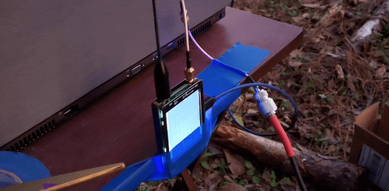
He needed a test spot out of the antenna’s near field so he set up his workstation 18 feet away from the test antenna which was on a mount that could rotate. On the edge of the workstation table — affixed with painter’s tape — is a NanoVNA connected to a laptop.
The rest is just sweat work. First, make a measurement on the resonant frequency. Then rotate the antenna 10 degrees and repeat. After 36 measurements you have the entire circle.
Plotting the resulting data with GNUPlot matched up pretty well with the antenna’s predicted performance. This was actually the second attempt and in the report, [Jephthai] reports that keeping alignment is critical to get everything to work. You can see in his pictures some of the steps he took to maintain consistency.
Another aid to consistency was the use of the NanoVNASaver software. This software allows for a frequency sweep along with a display and the creation of Touchstone files.
We’ve looked at the NanoVNA before. If you’d rather view your antenna pattern as a 3D volume, break out the 3D printer.


This is a simple setup to get a relative measurement of the antenna pattern. You need a known gain antenna to work out the absolute gain. There are also lots of extra stuff you need to take care of to get really good measurements. Such as ground reflections.
Also, anyone else note that the yagi and nanoVNA antennas are cross polarised in the photos. I assume they measured both co-pol and x-pol.
Having the antennas cross polarized only causes a reduction in the NANAVna received signal level. It would not have effected the actual pattern measurement as long as the polarization remained the same throughout the test.
No, it does more than that. Cross polarisation causes a very deep null. Slight changes in reflection or geometry can cause many dB swing in measurement.
In a ideal setup, a cross polarised antenna should have zero sensitivity( -inf dB).
The cross-pol Rx ant is too close to the laptop, too. Measuring the backlobe accurately is going to be a problem.
It would have been interesting to see both the H plane and E plane measurements.
Another way…
Near-field measurements are conducted by scanning a small probe antenna over a planar, cylindrical, or spherical surface. These measurements are then transformed to the far-field by use of a Fourier transform.
https://en.wikipedia.org/wiki/Antenna_measurement#Near-field_range_(NF)
https://en.wikipedia.org/wiki/Near-field_scanner