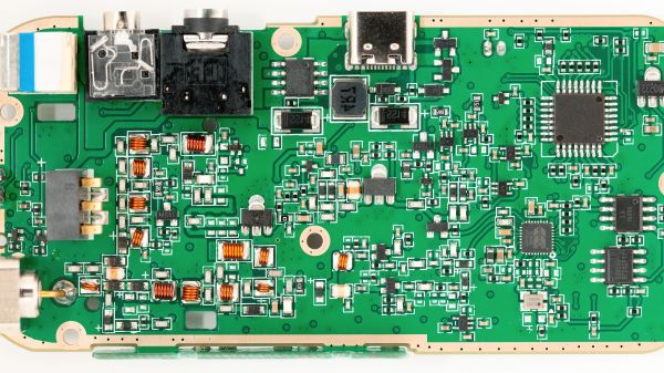
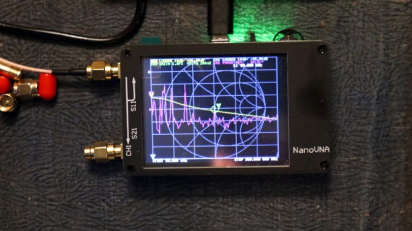
Reverse Engineering The Quansheng Hardware

In the world of cheap amateur radio transceivers, the Quansheng UV-K5 can’t be beaten for hackability. But pretty much every hack we’ve seen so far focuses on the firmware. What about the hardware?

To answer that question, [mentalDetector] enlisted the help of a few compatriots and vivisected a UV-K5 to find out what makes it tick. The result is a complete hardware description of the radio, including schematics, PCB design files, and 3D renders. The radio was a malfunctioning unit that was donated by collaborator [Manuel], who desoldered all the components and measured which ones he could to determine specific values. The parts that resisted his investigations got bundled up along with the stripped PCB to [mentalDetector], who used a NanoVNA to characterize them as well as possible. Documentation was up to collaborator [Ludwich], who also made tweaks to the schematic as it developed.

PCB reverse engineering was pretty intense. The front and back of the PCB — rev 1.4, for those playing along at home — were carefully photographed before getting the sandpaper treatment to reveal the inner two layers. The result was a series of high-resolution photos that were aligned to show which traces connected to which components or vias, which led to the finished schematics. There are still a few unknown components, The schematic has a few components crossed out, mostly capacitors by the look of it, representing unpopulated pads on the PCB.

Hats off to the team for the work here, which should make hardware hacks on the radio much easier. We’re looking forward to what’ll come from this effort. If you want to check out some of the firmware exploits that have already been accomplished on this radio, check out the Trojan Pong upgrade, or the possibilities of band expansion. We’ve also seen a mixed hardware-firmware upgrade that really shines.

RF Spectrometer Sees Inside

Spectrometry is a well-known technique or, more correctly, a set of techniques. We usually think of it as the analysis of light to determine what chemicals are producing it. For example, you can tell what elements are in a star or an incandescent based on the spectrum of light they emit. But you can also do spectroscopy with other ranges of electromagnetic radiation. [Applied Science] shows how to make an RF spectroscope. You can see the video below.

An oscilloscope-resident function generator creates a signal that he feeds to an amplifier because you need a fair amount of power going out. However, you also need to sense a very tiny amount of power coming back, and that requires a special circuit that will block high-power signals while passing low-level signals.

Continue reading “RF Spectrometer Sees Inside”

What Makes A Good Antenna?

It sometimes seems as though antennas and RF design are portrayed as something of a Black Art, the exclusive preserve of an initiated group of RF mystics and beyond the reach of mere mortals. In fact though they have their difficult moments it’s possible to gain an understanding of the topic, and making that start is the subject of a video from [Andreas Spiess]. Entitled “How To Build A Good Antenna”, it uses the design and set-up of a simple quarter-wave groundplane antenna as a handle to introduce the viewer to the key topics.

What makes this video a good one is its focus on the practical rather than the theoretical. We get advice on connectors and antenna materials, and we’re introduced to the maths through online calculators rather than extensive formulae. Of course the full calculations are there to be learned by those with an interest, but for many constructors they can be somewhat daunting. We’re shown a NanoVNA as a useful tool in the antenna builder’s arsenal, one which gives a revolutionary window on performance compared to the trial-and-error of previous times. Even the ground plane gets the treatment, with its effect on impedance and gain explored and the emergence of its angle as a crucial factor in performance. We think this approach does an effective job of breaking the mystique surrounding antennas, and we hope it will encourage viewers to experiment further.

If your appetite has been whetted, how about taking a look at a Nano VNA in action?

Continue reading “What Makes A Good Antenna?”

TinySA Is A $49 Spectrum Analyzer

The NanoVNA made network analyzers cheap enough for almost everyone. Now you can get a $49 spectrum analyzer to go with it. Is it worth it? Watch [IMSAI Guy]’s video after the break for his opinion. From the tinySA.org website:

  • Spectrum Analyzer with two inputs, high-quality MF/HF/VHF input for 0.1MHZ-350MHz, lesser quality UHF input for 240MHz-960MHz.
  • Switchable resolution bandpass filters for both ranges between 2.6kHz and 640kHz
  • Color display showing 290 scan points covering up to the full low or high-frequency range.
  • Input Step attenuator from 0dB to 31dB for the MF/HF/VHF input.
  • When not used as Spectrum Analyzer it can be used as Signal Generator, MF/HF/VHF sinus output between 0.1MHZ-350MHz, UHF square wave output between 240MHz-960MHz.
  • A built-in calibration signal generator that is used for automatic self-test and low input calibration.
  • Connected to a PC via USB it becomes a PC controlled Spectrum Analyzer
  • Rechargeable battery allowing a minimum of at least 2 hours portable use

A lot of cheap scopes and PC-based scopes can do spectrum analysis, too, of course, so this isn’t as exotic as a VNA. But at this price, having a dedicated instrument might be worth it to you, especially if you don’t care about frequency below 100 MHz.

There are some limitations, of course, but the price is right. [IMSAI Guy] shows a few oddities that he didn’t like, but overall, it seemed like a good value. If you have a modern scope it may already do this function, or you might be able to do a software solution. If you only need audio frequencies and you want novelty, try some ping pong balls Continue reading “TinySA Is A $49 Spectrum Analyzer”

So. You Bought A VNA. Now What?

It’s never too late in life for new experiences, but there’s a new experience I had a few weeks ago that I wasn’t expecting. I probably received my first piece of test equipment – a multimeter –  in the early 1980s, and since then every time I’ve received a new one, whether an oscilloscope, logic analyser, spectrum analyser or signal generator, I’ve been able to figure out how to use it. I have a good idea what it does, and I can figure out whatever its interface may be to make it do what I want it to. My new experience came when I bought a piece of test equipment, and for the first time in my life didn’t have a clue how to use it.

That instrument is a Vector Network Analyser, or VNA, and it’s worth spending a while going through the basics in case anyone else is in the same position. My VNA is not a superlative piece of high-end instrumentation that cost the GDP of a small country, it’s the popular $50 NanoVNA that has a fairly modest frequency range and performance, but is still a functional VNA that can take useful measurements. But I’m a VNA newbie, what does a VNA do? Continue reading “So. You Bought A VNA. Now What?”

NanoVNA Tests Antenna Pattern

When [Jephthai] wanted to build his own Yagi antenna, he turned to MMANA software for antenna modeling. This is an antenna analysis program that uses the moment method to calculate parameters for different antenna geometries. After building the Yagi, the predicted tuning and impedance matched the real antenna nicely. But what about the radiation pattern? To test that, he used a NanoVNA and a clever test setup.

He needed a test spot out of the antenna’s near field so he set up his workstation 18 feet away from the test antenna which was on a mount that could rotate. On the edge of the workstation table — affixed with painter’s tape — is a NanoVNA connected to a laptop.

Continue reading “NanoVNA Tests Antenna Pattern”