Everyone knows that one of the coolest things to do with a Tesla coil is to light up neon or fluorescent tubes at a distance. It’s an easy and very visual way to conceptualize how much energy is being pumped out, making it a favorite trick at science museums all over the world. But what would it look like if you took that same concept and increased the resolution? Replace that single large tube with an array of smaller ones. That’s exactly what [Jay Bowles] did in his latest video, and the results are impressive to say the least.
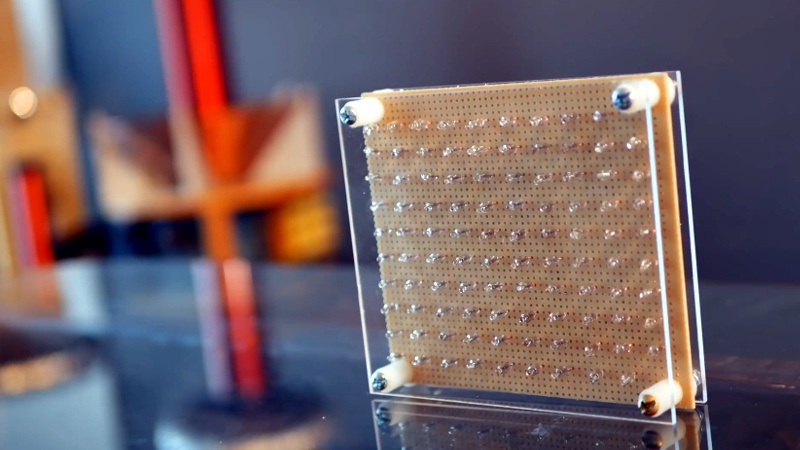
 From a hardware standpoint, it doesn’t get much simpler. [Jay] knew from experience that if you bring a small neon indicator close to a Tesla coil, it will start to glow when approximately 80 volts is going through it. The higher the voltage, the brighter the glow. So he took 100 of these little neon bulbs and arranged them in a 10×10 grid on a piece of perfboard. There’s nothing fancy around the backside either, just all the legs wired up in parallel.
When [Jay] brings the device close to his various high-voltage toys, the neon bulbs still glow like they did before. But the trick is, they don’t all glow at the same brightness or time. As the panel is moved around, the user can actually see the shape and relative strength of the field by looking at the “picture” created by the neon bulbs.
The device isn’t just a cool visual either, it has legitimate applications. In the video, [Jay] explains how it allowed him to observe an anomalous energy field that collapsed when he touched the base of his recently completed Tesla coil; an indication that there was a grounding issue. He’s also observed some dead spots while using what he’s come to call his “High-Voltage Lite-Bright” and is interested in hearing possible explanations for what he’s seeing.
We’ve been fans of [Jay] and the impressively produced videos he makes about his high-voltage projects for years now, and we’re always excited when he’s got something new. Most hardware hackers start getting sweaty palms once the meter starts indicating more than about 24 VDC, so we’ve got a lot of respect for anyone who can build this kind of hardware and effectively communicate how it works to others.


I’m pretty sure I remember seeing something like this here on HaD years ago. Except, for that one the light was moved all around the room all while taking a long-exposure picture. The result was a really awesome map of an electromagnetic field.
That light may have been an active device rather than a simple neon tube. I don’t actually remember.
Cool. I was thinking about something similar the other day, whether hall effect sensors react fast enough to a magnetic field that you can make yourself a wand lined with HES and LEDs and POV map magnetic fields by waving it around.
Edit: (why isn’t that button here yet :-D ) Also could be using accelerometers or other position sensing to be able to send sweep data back to some smarter device for mapping/storage. Phone or Pi or real computer.
Do you remember this older hackaday post about a spatial magnetometer?
https://hackaday.com/2017/08/07/imaging-magnetism-with-a-hall-effect-camera/
Thanks.
interesting and a great science project demonstration
but you can’t ground the thing and that plexiglass could develop some charge on it…. not for the inexperienced, perhaps.
So… why connect all the leads in parallel, vs alternatives like “one lead connected in parallel, one unterminated”?
I was thinking htat was a typo and the leads are just brought out parallel to the lamp. It would seem in they were all wired in parallel the first lamp to light would be the one with the lowest break down voltage and it would be hard to get the next one to light. If they are all independent, you still have the difference in voltage between them, but at least the first one will not shunt others out. I probably should watch the video. I personally don’t see this as being very useful or any more useful than a fluorescent or neon tube you can wave around the device and sniff out the hot spots with.
It’s not measuring the voltage across the leads of the neon bulb, but rather the external electric field across the narrowest gap inside the neon bulb. After all, if your hypothesis were true, one bulb in his array would always light first, and that’s visibly not true.
As to why the wiring both legs – my only guess is that it’s a cheap way to get a couple hundred pF of parasitic capacitance, so maybe it behaves as a cheap AC ground for high frequency signals like his tesla coil.
The narrowest gap between what?
I wonder if a repurposed plasma TV screen could be used …….
Carry around a convenient electrostatic source, like a nylon sack full of cats, so you can check one out if you come across one.
This isn’t so useful anymore, but until a couple of years ago you could stick some aluminum foil on the face of a color TV and have a very painful amount of electrostatic sourcing. I used this to make a set of Franklin Bells for some kids, and it worked great other than boy was it unpleasant when I was trying to get it set up and it kept arcing to me.
I remember turning off my portable TV with the physical power toggle button back in 2003, it gave me such a huge static shock my whole right arm went numb. I tended to switch it with a non-conductive implement after that.
I am wondering if you have so something like POV instead of getting more pixels (bulbs)
Been forever since I messed with NE51h, but I vaguely recall biasing them with a voltage below ionization caused them to be more sensitive to fields
So cool.
Ol’ stuff:
Bag of toy compass in a grid pattern and ‘magnetic beard’ toys. Add a cheap webcam and slice and stack photos. Havent got around to Hall effect array but so cheap nowadays. Not really sure which orientation would be best. Hall effect grid arrays are available but Tesla coil use may not be on the brightest ideas.
I’ll see your cute NE2 electric field indicator and raise you Richard Box’s _Field of Light_:
http://www.interactivearchitecture.org/richard-box.html
i remade it with columns wired in parallel, and added a banana plug socket connected to 1 leg of each socket, so each bulb is grounded on 1 side, which does increase the number of bulbs to light up & distance from source at which they’ll light.
i also got an acrylic sheet with grid of toy compasses, but it has to be perfectly flat /: maybe I’ll try again with spherical compasses, like they have for car windshields/dashboards…
Try the power tubes of a tube guitar amp? Plates are often 400-500v