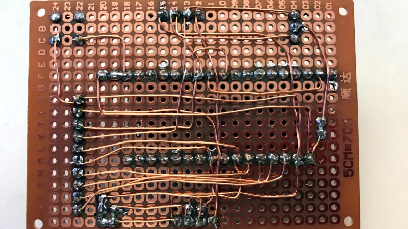
[Tom] doesn’t much like breadboarding. He prefers to wire up prototypes with perfboard and solder point-to-point with enameled magnet wire. That may sound troublesome to some of you, but [Tom] has come up with a few tips to make prototyping with perfboard and magnet wire easier and more effective, and the biggest tip is about how to manage stripping all that magnet wire.
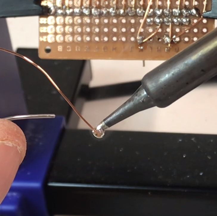
Magnet wire is a thin, solid-core conductor that has a clear coating of enamel. This enamel acts as an electrical insulator. The usual way to strip away the enamel and reveal the shiny copper underneath is to scrape it off, but that would get tiresome when working with a lot of connections. [Tom] prefers to “boil it away” with a blob of molten solder on an iron’s tip.
Begin by melting a small amount of solder on the iron, then push the tip of the magnet wire a small distance into the molten solder and hold it there for a few moments. The enamel will bubble away and the solder will tin the copper underneath in the process. The trick is to use fresh solder, and to clean the tip in between applications. You can see him demonstrate this around the 1:00 mark in the video embedded below.
Once the tip of the magnet wire is tinned, it can be soldered as needed. Magnet wire bends well and holds its shape nicely, so routing it and cutting to size isn’t too difficult. [Tom] also suggests a good hands-free PCB holder, and points out that 0603 sized SMT resistors fit nicely between a perfboard’s 0.1″ pads.
Perfboard (and veroboard) have been standbys of prototyping for a long time, but there are still attempts at improving them, usually by allowing one to combine through-hole and surface-mount devices on the same board, but you can see [Tom] demonstrate using magnet wire on plain old perfboard in the video below.


You can also use a match or lighter to burn off the enamel. Remember to wipe of the burnt coating with a paper towel.
This process leaves oxidized copper which is very bad to solder.
Using solder leaves a nice tinned end. However, it only works with “heat strippable” enamel
Yes, I used that stuff in the 1980’s but now it is tooooo heat proof.
That’s why you use flux :)
Flux is acidic, NONONO!
Am I missing a joke here or do you really not solder with (electronic) flux core 63/37? The acid flux you find in hardware stores and the solder wire containing it is designed for plumbing use.
That’s how I was first taught to do it.
But I don’t do that anymore.
I never did like that process. Maybe I used the wrong magent wire? It’s too hard to get every last bit enamel, burnt enamel residue and oxidation off. And the more you attempt to do so the more good copper you sand away!
There is specialized magnet wire with enamel that is designed to burn away clean at soldering iron temperatures. Just tin it and you are good to go!
I once saw a video where someone hollowed out an old soldering iron tip to use as a super-tiny solder-pot just for tinning these wires. If I ever again find myself soldering a lot of magnet wire that is what I will do.
Oh, and copper colored magnet wire? You have to be a real glutton for punishment to use that stuff! It’s way too hard to tell how well the enamel is or isn’t coming off!
1. I use this method exclusively for magnet wire because it works so well, but I clean off the residue with steel wool, which works like a charm. Perfect, actually, because it makes it easier to see where the insulation still remains. An important detail is to use the steel wool over the trash can so that none of the metal fibers can later create short-circuits. 2. For boost converters, buck converters, and other higher-power circuits that you might build, it is important to use thicker wire for the power paths, which using magnet wire allows.
Still…. For perfboard prototyping, even though we assume that enamel insulation won’t wear easily and might be better than plastic insulator, it will wear eventually. The problem is that, unlike the case of plastic insulators where you can easily see where insulation has worn off, it’s hard to detect undesired enamel removal with simple look. And it’s not like we can avoid enamel wearing, specially when soldering one wire’s joint near another wire.
But in other words transformers would age as well due to this? I have many old ones that are still fine. Though perhaps the later production methods are less durable of course, which haven’t been around long enough to show this.
Transformers’ (and electromagnet) windings aren’t subject to the kind of orthogonal configuration, handling, and movement that exposed wires on the bottom of a circuit board endure. This idea seems great in theory, but Murphy’s law says that two crossed wires will abrade against one another just when/where you need it least.
On the other hand, the coating on magnet wire found in automotive coils, starters etc… is well known to fail from heat and vibration over time. I definitely wouldn’t use it on a circuit board that was expected to endure even mildly harsh environments. I guess its ok for a prototype though it dont really see how it is more convenient to have to melt and tin wires that simply strip an insulated wire and stick it in a breadboard.
But this only works if you have the low temperature or self fluxing enamelled copper wire. And if you’ve bought that specifically, surely you’d already know that’s what you have. Am I missing something? Oh and what do you call tinned copper wire in Magnetwire land?
Wirewrap wire or just ordinary insulated single core wire is good for a variation of this technique, you can usually melt the insulation at 3 or 4mm away from the end and just pull it off by gripping the end with your fingers.
I recently had to connect multiple RGB LEDs in a chain/matrix. To save time I just used wire from LAN cable, wrapped it around each lead from LEDs and just melt the insulation and soldered it directly. It was a bit smelly but it worked like a charm…
How about NO?
The trick is to not use your own soldering iron for melting the plastic insulation, but self fluxing enamelled wire is fine, it’s designed to do this.
However, there are some caveats:
– many of these self-fluxing wires require high soldering iron temperatures (400-430 C or so) to actually burn the enamel off. That’s pretty unhealthy for things like LEDs, especially SMD ones.
– many of these wires release very toxic fumes – e.g. polyurethane-based enamels release stuff like isocyanates. You definitely don’t want to breath large quantities of that in while soldering, good fume exhaustion system (not just a fan) is a must.
I am using the products from http://www.roadrunnerelectronics.com and it does have both of the problems above.
Let’s not do that. Melting PVC is very very unhealthy.
I held my breath. And I don’t think that 1-3mm of partially molten insulation per joint would kill me. It would be better, of course, to use a fume extractor or protective gear…
According to RoHS and EU in general, using solder that contains lead is very, very unhealthy. Yet I know of at least one person who fixed radios and TVs for 50+ years and didn’t die from lead poisoning. And most of that older equipment used phenol-based PCBs…
BTW, a friend of mine had to deal with 60 liters of old transformer oil that was made of polychlorinated biphenyls. He got an old RTG head that was filled with the stuff. You don’t even know, how hard it is to safely get rid of the stuff if you are an individual with a strange hobby…
I’m not sure how this continues to persist, but: the main problem with lead in solder is not necessarily in initial usage. It’s when debris, ewaste, byproducts of manufacturing, etc ends up leaching it into soil and groundwater, if I understand correctly. You certainly can misuse leaded solder badly enough to injure yourself at the time, but I was under the impression the regulation was mostly to protect others from you and the whole supply chain/product lifecycle.
Burning the magnet wire insulation may also not be very healthy. Some types will release isocyanate compounds on exposure to heat. Definitely not as bad as PVC though…
I always wonder why the beautiful old art of wire wrap has vanished
I still do it. The sockets are expensive; often costing more than the chips. I still have some I salvaged from some surplus boards years ago. I can sit and watch TV and wrap wires from a net list or data sheets. Or at least I could before we got our new kitten.
PCBs are cheap, home stenciling is easy, and interesting chips in DIP are becoming scarce.
Yeah I always heard we have to buy the DIP. It’s written in the famous book “The Art of the DIL”
Another reason from the cost is that these sockets are very bulky.
Most electronics nowaday’s is also SMT. Lot’s of chips are not available in DIP packages anymore.
With soldering techniques you can botch almost anything together.
Funny, I thought everybody does it like that!
After looking at the video, a few further tips:
Use a wiring pen!
https://www.verotl.com/verowire-wiring-pen-part-number-79-1732
Not cheap for a piece of plastic, but worth it imho. You can hack one together out of a 0.5mm push pencil, but the metal parts of that can nick the insulation. After you’ve tracked down the first short deeeep in a bundle of wires, you’ll spring for the proper tool.
Doing it like in the video vs with a wiring pen is like crimping with your leatherman vs with a crimping tool. You’ll never look back.
Next tip:
You actually can simply wrap the wire tightly around the leg of a through-hole component, and then solder the leg to the perfboard. Easy to do with a wiring pen! The enamel of wiring wire will burn off while soldering.
(In theory, at least. For me that never was super reliable, so I burn the enamel of with the soldering iron as in the video)
Hth,
Alex
I wrote a how-to for Instructables some time ago on how to use the Verowire pen.
https://www.instructables.com/id/PCB-Prototyping-With-Verowire/
Nice writeup, thanks for sharing!
And: nice work on your perf boards :)
TL;DR: Warning about using magnet wire in circuits with high-speed signals in last paragraph.
When I was building my first computer, in a different century, I used blue perfboard with point-to-point wiring with what was called “wire-wrapping wire”, even though I wasn’t about to put out the kind of money that wire-wrap sockets cost (generally about 4x the cost of the chips, MINIMUM). This was because it was a readily available small-gauge (30 AWG, or 0.28mm) solid wire that stripped easily. Worked fine, except that if you soldered a wire that was crossing another wire close to where you were soldering, there was a high chance that the insulation would melt and the wires short together – the Kynar insulation isn’t especially robust, thermally.
I guess it’s still called “wire-wrapping wire”, even though nobody has wire-wrapped ANYTHING in about forty years (except maybe telephone people, but .. who?)
Anyway, I was very close to finishing the wiring of the first phase of the project, when I ran out of wire. So I decided to use 28 AWG magnet wire, since I had some on hand, and only had the interconnections between the CPU and video board and the memory board left do do.
Everything worked, with a few minor issues (two defective 2102 SRAM chips, and very little else wrong), as long as the two boards were set on the table side-by-side. And yes, this was the thrill of my young life, since I had just built my own COMPUTER, using nothing but my own skill and the somewhat confusing datasheets in early MPUs! But when I folded the boards together into what was to be their final position, I saw a bunch of incorrect pixels show up on the picture tube. I just had to say “picture tube”, because it’s a phrase I haven’t used in a long time. Not “CRT”; “picture tube”, which was part of a 5″ portable TV I had bought for the specific purpose of using as a computer monitor.
Opening the boards back up to troubleshoot, the problem went away, so with the system running, I folded the boards back together, and watched the random pixels come back. All that had moved were the interconnecting wires. So I moved the wires individually, and could make the problem better or worse just by moving these enameled wires. The problem went away when I bought some more wire-wrapping wire and replaced the interconnect wires.
My conclusion at the time (and no reason to revise that since) was that the enamel insulation was so thin, there was significant capacitive coupling between the wires. So that’s the warning. Wire isn’t just wire; it’s a component. I’ve used magnet wire successfully since then, but always avoid running signal wires in parallel for any significant distance.
you had a bad connection or a short
And you are basing this diagnosis on ….?
People in our factories still wire-wrap a lot. They’re the guys that make the “bed of nails” test jigs that hold PCBs down with vacuum.
They say the quick changing makes it easy to adapt to PCB changes and fix errors. As these beds of nails are made in super-limited quantities it’s not worth making PCBs for.
The main issue with enameled magnet wire is that you just can’t use pliers or tweezers to handle the wires. Because for sure you are going to scrape of a little of the enamel, especially if the pliers or tweezers are metal.
Not sure if you’re trying to imply that this may have been how this failed in my project, but this was not the case. I explored that possibility, and there had been no damage to the insulation.
“I guess it’s still called “wire-wrapping wire”, even though nobody has wire-wrapped ANYTHING in about forty years (except maybe telephone people, but .. who?)”
I did some last week (with a lot of point to point on discretes). See my projects. It’s expensive and sockets aren’t easy to find but it’s fast and easy to fix mistakes. Of course my projects are mostly pseudo-retro.
Wire-wrapping wire and magnet wire are totally different things.
Yes, I’m betting a short. Enamel insulation is thin and can be scratched through fairly easily. The only way capacitive coupling would be an issue is with high-Z inputs.
Whereas I am betting that the OP knew his game (think what it was he describes building) and both considered and rejected that possibility through experiment.
I’m happy that people are willing to second-guess my own diagnostics, but there was nothing wrong with the insulation. It didn’t matter WHERE the wires touched, and there was no other evidence of insulation failure. I spent a considerable amount of time ruling out everything else, and the inescapable conclusion, following the Sherlock Holmes method, that magnet wire was unsuitable for this. I am sharing this knowledge with others who may run into the same trouble, but of course everybody is free to ignore my conclusions and advice. Knock yourselves out..
Your hubris here is breathtaking. And not well founded. I know BBJim from other discussions and know him to be knowledgeable. Certainly knowledgeable enough to take his assessment of his own project as accurate.
On the other hand your statement about Cap coupling only being relevant to high Z inputs is not accurate at all. I wonder if you have thought about the problem space properly. The project has significant physical dimensions so longer signal routes are likely, it is a digital design that is also likely to have reasonably high frequency signals and fairly sharp edges as well. If it is also noted that one essential concept is that any consideration of the circuit based on lumped elements of capacitance and or inductance is an approximation and the only accurate analysis is transmission line analysis. So to combine all these factors would suggest that the parallel conductors act as coupled transmission lines that are carrying signals which are likely to be synchronous and also likely to have timing constraints that are not trivial.
I have seen exactly this type of problem myself in designs where the project engineer has let an auto router do its worst and generate bus signals that vary between the ‘manhatten length’ and around double the manhatten length from one bit to the next in a single bus. In that case the problem was mostly just timing margins and in this case for BBJim the same may well be true if the signals in the adjacent wires were changing in opposite directions for example.
It does not necessarily take a high Z node net for this effect to occur. These are transmission lines and as such have an impedance as do the transmitters and receivers. The effect that BBJim describes is highly plausible. your comment that it could not be Cap coupling is not correct without caveats that would be unlikely to apply in this case anyway.
My only comment to BBJim would be: if you don’t like the Tx line approach, could it have been inmductive coupling or a combination of Cap and Inductive coupling? ;-) (I’m sure you know where I am heading with this.)
Oh, and BTW, how can so many of you think that enamel insulation is easily damaged? I have only ever had a horrible time trying to strip the enamel off! Was I ever pleased to discover polyurethane magnet wire though. :-)
Hi, Stephen, thank you for your insights on this.
I love to tell a story, but my main reason for commenting in the first place was to warn people about this hazard when using wire with very thin insulation in point-to-point wiring. If people want to ignore my warning, I don’t have a problem with that. However, I DO have a problem when they do a disservice to others by just dismissing my warning with “must have had a short”, implying to others that there is no problem with using enameled wire in point-to-point wiring, as long as you are careful not to nick the wires.
Now, this was about forty years ago, so I don’t have documentation for any of this. But I’ll give enough information about the case for people to make their own decisions about whether or not to consider my warning.
First, this was a system using Intel 2102A SRAMs as the video RAM, and 74LS93 counters through 74LS157 2-input multiplexers for the address and data lines. As such, this involves low-impedence drivers feeding high-impedence inputs for the address lines, and also for the data lines when writing to memory. For reading, the data lines being driven by the SRAM chips were low impedance driving medium-impedance LSTTL inputs. The MPU and video counter circuits were on one perf board of about 10″ x 4.5″, and the memory arrays (both main and video memory) were on a separate board of the same size. These were mounted on a hinging arrangement along the long edge of the boards, so they opened up like a restaurant menu. All of the logic was on the MPU/logic board, including the multiplexers; only the SRAM chips themselves were on the memory board.
At the point I ran out of Kynar wire, the addresses were completely connected; the only signals that were wired with enameled wire were the data lines between the data multiplexers and the SRAM chips’ data lines.
The symptom showed up as video “noise”, that is, pixels whose states were unstable, showing white intermittently when they should have been black, and vice-versa, where by “intermittent”, I mean that the pixels changed at a high but random rate. The design of the system was such that the video memory data was loaded in parallel as 8-bit words into a shift register (don’t recall the type, but it was a 74LS series chip), which mapped the bits to horizontal positions on the screen. Thus I could see just by what position the bad pixels were, which data bits were responsible.
What I observed, was that there were multiple bit positions that had errors, and that I could affect which bit positions had errors, and how severe the errors were, just by moving the interconnecting wires. It is my recollection that most or all of the bits could be made to exhibit the errors by moving different wires. The errors did NOT exhibit the solid wrong values that a direct line-to-line short would have caused. The errors appeared as “ghost” images, i.e., not as solid as the expected images. The errors appeared to be errors on read only – errors disappeared when the wires were separated, with only the correct data remaining, even when new data was written while errors were visible on the screen.
For a short while, I operated the system with the boards unfolded, which allowed the interconnecting wires to move away from each other and from other wires, with no other problems. Upon replacing the enameled wires with Kynar-insulated wire, the problems disappeared, and did not return over the three or four years I was using this system. I DID have to replace two of the 2102A chips at some point along the way; whether this was due to actual chip failure, or marginal timing in the system, I did not determine. In both cases, the failure mode was an “always on” column of pixels, indicating a stuck bit. I was able to make the symptoms go away by replacing the chip responsible for the bit in question (these were 1024×1 chips), so I treated this as “problem solved”. Since this was meant to be my own hobby system and not a prototype for a production computer, I didn’t worry myself too much about finding the root cause.
The interconnecting wires ranged from six to twelve inches in length, and the data was being multiplexed between the MPU bus and the video counters, switching at about a 2 MHz rate. I don’t know the exact rise/fall times, but they would have been in the 10-50 ns range, but I would not have had any means to measure this at the time. Just the same, this would have been way too slow for transmission line effects to be dominant, which is why I concluded that this was a lumped capacitance issue. Also, the difference in inductance between 9-inch fairly-straight pieces of 28 AWG magnet wire and 30 AWG wire-wrap wire would be insignificant, so I believe the fact that changing the wires remedied the problem definitively, rules out this being an inductance issue.
Hopefully, this is enough additional information that people reading my previous comment can determine for themselves whether this was, as I concluded, a distributed capacitance issue, or “just a short”.
Wow, that brings back memories. Worked to my advantage though. Needed a few ns delay so the first character showed on the crt. Twisted two pieces together which made a capacitor, it worked.
Kynar (wirewrap) dielectric constant ~6.4
Formvar (magnet enamel) dielectric constant ~7.4
I threw those numbers into an online EMI calculator. 30awg has a 0.005″ radius. Typical nominal insulation thickness at that gauge; of Kynar is 0.004″, of enamel coating is 0.0006″.
3″ of parallel 30awg Kynar at 0.018″ center-to-center distance has a capacitance of 1.189e-11 F, or 12pF
3″ of parallel 30awg Formvar at 0.0112″ center-to-center distance has a capacitance of 3.229e-11 F, or 32pF
They are worst-case numbers assuming two parallel wires in perfect contact along their entire length. At 1MHz, 32 pF has a 5kOhm impedance. That’s a 1mA worst-case drain. A TTL output that can source 16mA.
Your warning to treat wire is valid, especially in the modern age where CPUs are running at radio frequencies, but I think that your fault was far more likely due to either a dry joint or short, than capacitive coupling. I’m just not convinced that pF capacitance caused those issues in TTL at single digit MHz.
I don’t have any to measure at hand, but I think your thickness number for Kynar is way off, like by an order of magnitude or more. The insulation makes up about the same portion of the overall diameter as the wire itself, IIRC.
Ooops – my mistake. I was reading that one decimal place off. However, I still question your numbers: since there is a linear relationship between plate spacing and capacitance, if there is about a 7:1 ratio in insulation thicknesses, there should also be a 7:1 ratio of capacitance. Don’t know how you’re getting only a 2.5:1 ratio. Perhaps it’s your “center to center” measurement, which I don’t understand. If the wires are in contact, then the spacing between conductor SURFACES (which is what matters for capacitance) is equal to two thicknesses of insulation. Center-to-center has no meaning here.
Check the equations for two parallel wires if you don’t believe me. Capacitance is proportional to L/arcosh(D/2r) where D is center-to-center. 2.5:1 is correct.
That equation assumes a uniform dielectric constant, in particular bare wires in air, which is not the case here – in this case the dielectric constant is much higher at the contact point than elsewhere, so the formula you’re using does not apply. In this case, it’s closer to a plate capacitor.
I don’t know why you are unwilling to accept that I RULED OUT both open and short circuits, but I very much did.
If you have a look at a data sheet for an 8051 uC from some years ago and in particular the variants produced by Philips et al which ran at higher than the 16MHz limit (note clock frequency is internally divided down by 12 I think before it becomes the system frequency for the CPU) and even at these very modest frequencies there are still timing constraints between related signals (in particular and if my memory is correct) the timing of the output enable inactive for the programme memory and the bus being driven for the next bus cycle by the CPU was in single digits in nano seconds. So modest clock frequencies are not the only indicator to be considered. It is still possible for timing issues in a few ns even with cycle times in us.
First of all, this was a 2 MHz signal, and second, the frequency doesn’t mean anything. What you need to know in order for the impedances to be correct is the highest frequency COMPONENT of the signal. Like I said, I don’t know what the rise or fall times were, but at 10 ns, there would be significant components to at least 30 MHz.
Sorry – that was for ID.
I would agree with you, though the wire wrap wire also has similar effects. I used to do a lot of wire wrapping, I worked in a place that made prototypes and one off’s, and occasionally people would ask why the “spaghetti” was not tie wrapped together. Cross talk became much more of an issue. BTW, the industrial wire wrappers used 26ga wire and we had both 120V and pneumatic wire wrap guns. The pneumatic ones were the nicer. We also used proper sockets and those little shields you put on the back where you could write in the chip number with a sharpie and it had the pin numbers printed out. We did a lot of complicated boards. We would figure out the layout first, than plant the parts, and than work out a node list so at the end it was just U27-4 to U11-13 etc.
As far as your parasitics go, one of our guys had an office on the 4th floor and someone ran a shielded cable up from the basement where the computer was to his terminal. He could only use his terminal at 300 baud when I got there. You could almost type that fast. Not really, but it was painfully slow. I did the obvious, re-configured the port to 9600 and got nothing out of it. I could get 1200 to work a bit.. I thought about it for a while and looked at the set up and the guy that wired it did it what you would think was right, he had the shield grounded. I pondered though that it looked like a cap, and for fun ungrounded the shield. Poof. I think a lot of people made that mistake. With RS232, the voltages were high and the polarity reversed so it was pretty immune to noise, but it was limited to like 45ma, so it was sensitive to the capacitance of longer runs. I suspect for a very long run unshielded cable would have been even better, but that was the longest run I ever had to make. We did longer runs at another place but we used short haul models.
Brings back memories. I had a client who was trying to run an HP pen plotter about 50 meters from his computer. It seemed to work, but very slowly. It would plot a line, wait a few seconds, then plot the next line. Long story short, the cable plugged into the plotter had only Tx, Rx, and ground connected, and this was connected to an extension that went the rest of the way. The extension had all wires connected. This resulted in the CTS pin picking up enough noise that the computer was being stopped between every character.
I attended a data communications course at Exeter University in 1985, where they mentioned that some of the campus connections were using 3-core UK mains cable for links, and “with some connections we’ve found we can get away with only using 2-core; we presume the ground connection is being provided via the mains earth”
Fume extraction!
Do it!
You are burning plastics in your face and the evaporating lead does not help either.
Forget about this crappy fans with the coal-foam. If you can not vent to the outside, build or by yourself a decent one with real active-coal-filters. Active-coal is cheap when you by it from aquarium-supplies.
Please!
JAK
i don’t think soldering irons get hot enough to vaporize lead
If you are vaporizing lead, then you better put away that blowtorch and get a normal soldering iron. Soldering irons don’t reach anywhere close to the temperatures needed to vaporize lead.
For professional use: unmitigated, resounding YES, fume extraction is a must.
For occasional DIY: well… of course it’s a good idea as always, but it really is not that much of a big deal. But don’t take my word, take some numbers and arguments:
The toxic compound released when burning the enamel is tolouene diisocyanate [1] (TDI). The wire diameter is 0.2mm, insulation thickness is 5um [1]. Let’s say you burn 2mm off, and the isolation is 100% TDI, with the density of TDI 1.214g/cm3 [2]. This gives about ((0.1e-3+5e-6)^2 – 0.1e-3^2)*pi * 2e-3 * 1214 = ~8ng TDI per connection.
If you look at a typical column of smoke while soldering, that’s maybe 20cm high and 1cm diameter, or a volume of smoke of around 0.5e-2^2*pi*20e-2 = ~15ml.
This gives a concentration of TDI in the smoke of 8ng/15ml = ~0.5 mg/m3
The OSHA limit for TDI is 0.14mg/m3 [2], so 0.5mg/m3 is like 3.5 times the allowable limit.
This means: DON’T inhale the column of smoke! However, even if you inhale it, you’re not gonna die, the LC50 of TDI is 610mg/m3, over a thousand times higher [2].
If you dilute the smoke of 1000 connections over the 1m3 of air directly over your workplace, you end up with 8ug/m3, or 6% of the OSHA limit.
All that said, TDI is a (suspected) carcinogen, so avoid _occupational_ exposure as a matter of principle.
[1] https://www.verotl.com/verowire-wiring-pen-part-number-79-1732
[2] https://en.wikipedia.org/wiki/Toluene_diisocyanate
The LC50 is not really the issue, it is the hypersensitivity which can develop to isocyanate compounds evolved by thermal degradation of the polyurethane, which can subsequently cause hypersensitivity reactions and life threatening asthma within hours of re-exposure. Any hot process involving polyurethanes can cause this problem, i.e. weld through sealers, burning PU foam, hot wire cutting foam, laser cutting foam, or welding and grinding automotive panels with PU based paints. There is some evidence for hypersensitivity potentially being caused via skin exposure too, not just inhaled fumes.
still:
For normal DIY scenarios holding your breath while the whiff of smoke passes means you’re down to below percent-of-OSHA-limit levels in the air in your workshop. I agree that you do NOT want that on a regular, i.e. occupational, basis. But for very occasional DIY cases, I just struggle to see life threatening asthma attacks as a significant increase of life risk over all other risks.
I’m not trying to be snarky but look to be educated: would you have more details, preferably with numbers, as to the actual risk for rare and low exposure?
Only some individuals are prone to developing hypersensitivity; often those with a history of asthma.
Regular exposures would typically lead to hypersensitivity, if it is going to occur, within a year or so.
Once hypersensitivity has developed, RPE is not considered sufficient to protect such individuals from hypersensitivity reactions, which can occur at trace levels well below maximum allowable exposure limits. Such individuals simply have to be removed from environments with the potential for further exposures.
There is a published case report of a contractor working from home with a solder pot who developed occupational asthma tinning wires for their employer. I’d have to dig to find it though. Most of the literature on soldering and asthma relates to colophony lung, from rosin flux.
The idiosyncratic nature of the development of hypersensitivity in jobs involving exposure to isocyanates is why regulators typically require yearly spirometry as part of the work site’s health surveillance program, regardless of measured levels of airborne isocyanates or demonstrated local exhaust ventilation system effectiveness.
Ugh. The kids these days and their funny misconceptions. Solder smoke is not lead. Lead doesn’t vaporize at soldering temperatures. The lead is all in that little puddle that sticks to your board which you most certainly are not breathing. Solder smoke is just burning rosin. It’s basically burning pine tar. No smoke is great for you but it’s nothing like inhaling lead!
Now that chemical soup at the core of lead-free solders.. that stuff is scary.
Those European and Californian laws which through the power of market forces get applied to the rest of the world too.. those aren’t protecting factory workers who stuff boards. They protect people that drink groundwater in the vicinity of the landfill you send your toys to every few months when the new shiny comes out.
I will agree with you on the burning plastics though. That is never a good idea.
That’s why I keep my good ol’ 1lb spool of kester 63/37 solder. It’s wonderful to work with, eutectic, and with how slow I go through it, probably safer than the shit in lead-free solders.
I was teaching my kid how to solder with an elecraft fm radio kit, which came with a little tube of lead-free solder. He wanted to use it since it was small and came with the kit. He got half-way through it before it got misplaced, and when he switched to leaded 63/37, he was amazed at how much easier it was to work with. He’s 8, and he noticed how much easier it was to work with.
Of course lead evaporates at soldering temperatures. It will not boil, but some of it will evaporate. Water also does evaporate at temperatures below boiling, as will every liquid substance. The boiling flux will also send some lead particles in the air.
Hmm, I’ve always had an issue with burning the plastics away leaving behind black oil goo that prevents tinning and needing even more vigorous scraping to wet than just scraping the plastic away in the first place would have been…
That may be because magnet wire != wiring wire. At least not all _magnet_ wire is suitable, so ymmv…
The enameled wire sold for pcb wiring (eg under the brand Verowire but there are others) is self-fluxing to avoid the problem you describe.
Using an open flame will not only melt the plastic or enamel, it will also oxidize the copper. So that’s why it won’t tin.
Another trick I’ve learned long time back to strip away the enamel coating is placing the magnet wire (or bundle of magnet wires like headphone wires) on an aspirin pill and heating it up with the soldering iron. The heat along with the chemical in the pill melt the enamel layer away. Solder will stick to the copper after that. This works especially well for headphone wires, or the tuning coil off an AM radio. Don’t breath the smoke coming out from the burning aspirin. It smells quite bad.
Salicylic acid as flux? Great hack, have to remember that!
There is so little aspirin in an aspirin tablet. The tablets are mostly composed of fillers (e.g. silica) pigments (e.g. titania), lubricants (e.g. glycols), binders, etc.
It probably wouldn’t give you a headache though!Or if it did, you wouldn’t know :-)
Interesting idea though. Makes me wonder how it was discovered. How many random experiments do people do!? What sort of crazy stuff do people try? Funny and bewildering all at once.
By far the best prototyping is done by elm-chan.
I suggest to check all of his projects.
He posted a small tutoral: http://elm-chan.org/docs/wire/wiring_e.html
One thing to keep in mind is a lot of the enamels used to coat these wires is corrosive to soldering iron tips. The resulting stuff on the tip of your iron will eat right through it. Standard techniques for cleaning a soldering iron tip will not get rid of it.
Easiest way to deal with it is get some cheap tips / a cheap backup iron if you are going to be doing this. I’ve got a second iron with a big fat tip which makes doing this sort of thing very quick and easy.
Millenials invented enamel wire.
Great
Right? Everything old is new again. My favorite is “cohabitation space.” You mean an apartment with roommates?
The term “space” gives me associations with 3D. An apartment is 2D in my vision, you occupy the floor. 12m^2 is 12m^2 to occupy.
But “cohabitation space”… That sounds just super! 30m^3 is so much larger than 12m^2!
FTFY
That sounds just super! 30mm^3 is so much larger than 12mm^2!
That phrase is going to be an invention not of “millennials” but of (real) estate agents. They’ve always tried to dress up depressing living conditions with cosy sounding euphemisms.
“Timeshare” – The 4D Ownership (TM pending)
That sounds like an Apple product, tbh
https://hackaday.com/2016/08/09/hot-wire-strippers-are-probably-the-best-tool-you-arent-using/
I’ve learned this technique through this site: http://elm-chan.org/docs/wire/wiring_e.html
and used it in my DIY FPGA dev board: https://hackaday.io/project/33754/gallery#f7fcc8c8608beefe5cf8a6f64d4c69e5
Do people not own tins of flux any more, so you can dip it in to speed up the enamel cleaning.
Has anyone tried this with a solder pot? You could have just enough solder depth for the length of bare wire desired.
One of the 1st things I learned when I graduated from breadboards to more “permanent” looking prototypes, was that no matter how clever you get with your technique, point to point wiring on perf-board will always suck and look like trash once you get over about a dozen components. I still breadboard for quick testing but after that the CAD comes out. I if absolutely need a board ASAP I would etch my own in a heartbeat before I put myself through the pain of perf-board again.
Yah. I’ve graduated from perfboard to veroboard to stripboard over the years. It’s better but nowhere near good enough. If you check out the ham radio homebrew crowd they do some awesome things with manhattan style construction.
I’ve kind of had my fill of this sort of thing though and am currently studying up on KiCAD and FlatCAM. I have had a little success with chemical etching at home but I hate the mess and it never turns out as well as hoped for.
I don’t use magnet wire but 30 awg wirewrap wire for point to point soldering. Easy to strip. For power lines I use 22 awg hookup wire. To make bus bar I remove all insulation and solder at every point along the path.
30awg is way too thick for a prototype data bus, the wires get in each other’s way and it quickly becomes unmanageable. This wire is like jumper cables compared to what you need for passing signals. Much better to use 38 or 40 awg magnet wire with a tool. For modern microcontrollers you can use 30 awg for power. Check the link to elm-chan above to see how the maestro does it.
Most solders for electronics weakly dissolve copper. Wires 40 AWG and finer actually get eaten up pretty quickly, making soldering and removing enamel with a soldering iron difficult.
I do something similar with kynar. A little solder on the iron, melt the insulation and tack it down. Do it right and it can be as simple as: solder to point a. Stretch to point b. Solder it down and snip. Obviously this is for low power applications. Magnet wire would be useful for higher power stuff.
4-0 (0000) steel wool also works. Quick and easy.
Or just a postage stamp worth of abrasive paper. 250 grit or finer though.
IDK if that was too cryptic or it’s obvious you fold it over and just twist back and forth on wire or not.
I’ve always used #30 Kynar (Never PVC) insulated wrapping wire for my prototyping.
The soldering iron melts the insulation easily in just the right place without fowling the tip or creating toxic smoke.
The wire is already tinned and solders really well. Oxidation of the wire is never an issue.
I was once faced with the task of stripping multi stranded enameled wire that was thinner then baby hair. It was similar to the wire found in a pair of Apple wired earbuds. The individual strands were way to thin to run through sandpaper or steel wool because the wires would just snap. The technique I found worked best for stripping the enamel was to dip the end in a concoction of molten salt and Lye. The technique is documented here:
https://youtu.be/B9MimqTtLgg
I bought a small crucible on Amazon and heated the salt/lye mixture up on my kitchen stove while holding it with a pair of tongs. The process worked like a dream. Just dip the end of the enamel wire into the molten mixture and the enamel bubbles clean off in a very satisfying way. After rinsing the end of the wire with water, nothing was left but beautiful bare copper strands.
Of course it goes without saying that the mixture is very caustic and extreme care should be taken
https://en.wikipedia.org/wiki/Litz_wire ?
Cool! Never heard of this.
I did this a long time using a homemade wire pen with a bobbin and tiny steel tube. My only cost was a roll of 28 or 30awg green low temperature enamel magnet wire. It worked pretty good and didn’t have any issues with shorts between wires. Although the wiring looked messy, the wire bundles were much smaller and the soldering was quicker. I didn’t pre-tin, just placed the wire on the joint and applied heat (iron set higher than normal) with one continuous wire. After a bunch of wires soldered, used a sharp xacto knife to cut out the in-betweens.
The fastest way to strip thin enameled wire is a cigarette lighter. Anything over 1mm is a job for either a knife or sand paper. Sometimes it neads a little cleaning up with some extra fine grit wet and dry but it’s definitely quick. Just remember to be quick when you blow out the fine stuff :D
I’m not a fan of magnet wire for prototyping. It’s hard to tell at-a-glance if the insulation on it is properly stripped off, and thus, whether or not the wire is properly soldered on. It’s also hard to get solder to stick to it in general.
My general go-to for jumpering stuff is 30 AWG PTFE insulated wire. The smaller gauges of PTFE wire are still possible to strip by mechanical wire strippers (thicker stuff requires thermal strippers.) The PTFE insulation also handles heat a lot better, so the insulation doesn’t peel back while soldering.
Yucky! I much prefer to use emery cloth or an emery board. I guess if I had a lot of stuff to do the ends of I might get one of my old pencil irons out and let it get all disgusting, but stripping the plastic enamel insulation off of most modern wire with a soldering iron and a blob of solder just (IMHO) gets your tip really disgusting. You can cut plastic with a soldering iron room, in fact I did that not too long ago to make some little U openings in the battery box of an LED headlamp so I could run a wire down to some D cells on a belt clip so it would run bright for an entire day, not just a couple of hours. I also used one of my old fixed temp, 120V plug in irons that I don’t care much about. I tend to like a really clean tip.
Tinning magnet wire in a solder pot has been around for maybe 100 years?
Someone may have already picked up on this point but if this were actually enameled magnet wire no soldering iron is going to melt the insulation. Enameled wire is fairly rare now. What is used now is polyurethane in place of the enamel. And polyurethane can be used as the article describes and I use it for exactly the same purpose as the article describes.
I’ve heard all manner of methods for stripping enamel but I’ve never had much luck with any of them other than mechanical removal by scraping or abrasion of some kind. Polyurethane though is easy to strip if you just turn the temp of your iron up a little and be sure there is active flux in the molten solder then you just need the bare Cu (at the cut end) to be in contact with the molten solder to get the heat under the insulation and voila! :-)
I was told once that the polyurethane acts as a flux which was the explanation for its trade name ‘solderite’ (spelling optional) but anybody who has used it would I am sure agree, it makes a very crappy ‘flux’.
All you sandpaper freaks are missing the point.
How do you sand just enough of the middle of a wire to connect to the pin of a component?
With self-fluxing wire and a dispenser pen you can wire all the nets then solder only the bits than need to conduct.
I really thought this was common knowledge. That is, that’s how I learned to do it. Stretching to a new joint is as easy as using the right tip (bevel or hooked), good flux, and “scraping”. Once you get the hang of it, you barely have to cut your enameled wire.
It’s not just common knowledge – it’s a product feature.
I somehow missed this thread.
I’ve been using this technique for years, and it works pretty well, though it’s time consuming.
“enamel” is a weird name for this (though it has stuck for a long time) It’s not “enamel”, 2 layers of lacquer seem to be common, a polyester, and a polyurethane layer. Enamel is probably too brittle to have ever been used for this.
Some tips:
@ 01:10 you see that the wire does not wet very well. It takes some time to get to the soldering temperature because the lacquer isolates the copper, and the copper conducts heat away into the wire. This can be partly remedied by starting from the very tip of the wire. The cut end of the wire does not have lacquer on it but is bare copper, so there is no lacquer to hinder heat transfer. The cross section of the wire also wets easier because it’s clean copper, and wets at a lower temperature (thus faster) because the melting temperature of solder is lower then the melting temperature of the lacquer. Once the cross section of the wire is wetted, heat transfer increases a lot which improves speed.
A hot soldering iron is very beneficial, or often even mandatory. I often use 400 Celsius or crank it up to the maximum of 450 Celsius.
It is also handy to have 2 soldering irons.
You use one soldering iron at a hot temperature and use it just for burning the lacquer. The other can be a lower temperature just for soldering the wires to the board.
He’s using a “third hand” to hold the wire. These things are of bad quality, and not needed at all.
It’s much easier to have a stand for your soldering iron in which the tip is accessible without taking the soldering iron out of it’s stand. This way you can use one hand to hold the wire, and the other hand to hold the solder.
Thinner wire is often easier. I use 0.2mm diameter wire the most, and it can handle a few hundred mA.
The wire can easily be manipulated with pliers or tweezers, but make sure there are no sharp edges. Sometimes your tools get slightly nicked, which can leave a sharp burr. Use your fingers to check for these and use some sandpaper or whetstone to remove them.
The latest technique I’m experimenting with works as follows:
1). Place DIP sockets on a Matrix Board and mark their locations.
2). Remove the DIP sockets.
3). Place pre-cut pieces of wire through the holes. (from the “component” side).
4). Put the DIP sockets back.
5). Wrap the wires once or twice around the DIP socket pins.
6). Cut the ends of the wires.
7). Solder all connections.
It seems to work a lot quicker, but I have not used it enough to perfect it. Not many of my projects use DIP IC’s anymore these day’s.
Just torch it first, don’t abuse your tools and risk contaminating your solder points.