If you’ve seen both a fused filament fabrication (FFF) printer and a wire welder, you may have noticed that they work on a similar basic principle. Feedstock is supplied in filament form — aka wire — and melted to deposit on the work piece in order to build up either welds in the case of the welder, or 3D objects in the case of the printer. Of course, there are a number of difficulties that prevent you from simply substituting metal wire for your thermoplastic filament. But, it turns out these difficulties can be overcome with some serious effort. [Dominik Meffert] has done exactly this with his wire 3D printer project.
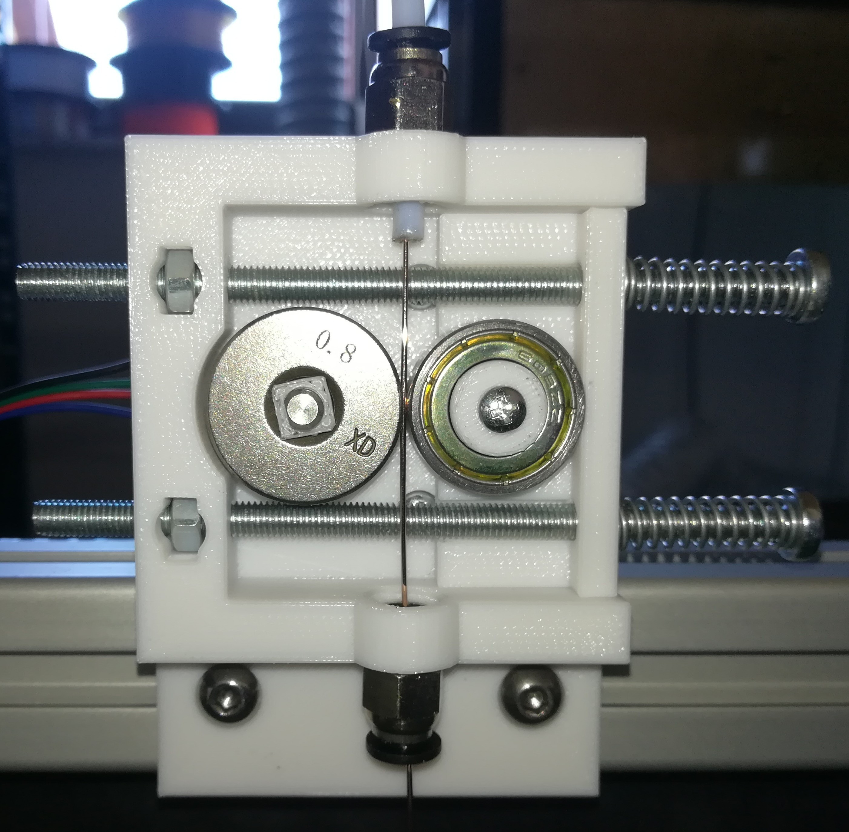
For his filament, [Dominik] chose standard welding wire, and has also experimented with stainless steel and flux-cored wires. Initially, he used a normal toothed gear as the mechanism in the stepper-driven cold end of his Bowden-tube extrusion mechanism, but found a standard wire feeder wheel from a welder worked better. This pinch-drive feeds the wire through a Bowden tube to the hot end.
In thermoplastic 3D printers, the material is melted in a chamber inside the hotend, then extruded through a nozzle to be deposited. Instead of trying to duplicate this arrangement for the metal wire, [Dominik] used a modified microwave oven transformer (MOT) to generate the low-voltage/high-amperage required to heat the wire restively. The heating is controlled through a phase-fired rectifier power controller that modulates the power on the input of the transformer. Conveniently, this controller is connected to the cooling fan output of the 3D printer board, allowing any standard slicer software to generate g-code for the metal printer.
To allow the wire to heat and melt, there must be a complete circuit from the transformer secondary. A standard welding nozzle matching the wire diameter is used as the electrode on the hot end, while a metal build plate serves as the other electrode. As you can imagine, getting the build plate — and the first layer — right is quite tricky, even more so than with plastic printers. In this case, added complications involve the fact that the printed object must maintain good electrical continuity with the plate, must not end up solidly welded down, and the fact that the 1450 °C molten steel tends to warp the plate.
Considering all the issues that have to be solved to make this all work, we are very impressed with [Dominik’s] progress so far! Similar issues were solved years ago for the case of thermoplastic printers by a group of highly-motivated experimenters, and it’s great to see a similar thing starting to happen with metal printing, especially using simple, readily-available materials.
This isn’t the only approach to DIY metal printing, though. We saw one that used electron beam melting (EBM) not too long ago.
Thanks to [Krzysztof] for the tip!


Well, it’s doing something – and it’s a great effort to even get to that point. I’m surprised though that particularly with a process that won’t allow bridging we’re still stuck with 3-axis machines. I’m not saying “go all in right now and combine it with a milling spindle to finish surfaces every now and then… but 4 or 5 axes to manipulate the work never made more sense – one could build up welds from all sides. One could even attach broken parts, add a 3D scanner and rebuild them.
Weld wire may have a great potential for bridging, it may not look clean but I could see starting an arc, fusing, cut the power extrude just like an pla printer, then start the arc back again and finish it, it would be “stringy” until you have enough wire filiments. One interesting thing about welded is the ability to control the power/heat, it is a bit more instant than plastic 3d printing.
Many of these all have a similar issue with spatter and cleanliness of starts/stops. Perhaps using very fine wire 1/32 or so you could have something that looks decent without lots of clean up at the sacrifice of speed.
Some argon or co2 blanket gas may make this look much better. perhaps water cool the bed?
I always thought ya might just fill the whole build area with something like mineral spirits. Instant cooling. I was a welder, and we used to do this by hand of course. We used copper plate to build on. But you could make a part, it just didn’t like being reworked too much because of the grain of the metal is more like glass after a liquid transfer. His lower temp approach will probably help with that.
I like the sound of that, would definitely help with some of the warping. Reminds me a bit of those plasma cutter tables that keep a big pool of water underneath the work piece. Or better yet, like a Resin 3D printer that uses the laser to “harden” the liquid, it immerses, and emerges as needed during the laser run, so it’s curing just that thinnest layer of resin on the edge of the work. If you had it in a mineral oil bath, and immerse/emerge it as needed, to help spread the thermodynamic build-up stress a bit. Might help?
How did you deal with mineral spirits being flammable? Seems like that could make welding a bit, er, interesting.
I’ve always thought you could enclose the entire machine in a tank filled with welding gas to avoid any oxidation. Cooling might not be very good but you could take it slow and it might yield better results.
The roller in the picture is for 0.8mm wire, which is just over .031″, which is just under 1/32″. You can get smaller wire than that, but shielding gas would probably be a better next step.
Yeah, there’s definitely a problem with shielding gas there, also I think he’s running the wire a little hot?
That won’t work well… The carriage would have to bend the wire at 90degrees as it moves it across the gap. It would look like absolute garbage or cause it to skip steps.
Just a thought: if the carriage had a two-axis tilt and rotate, you could lay down cold wire for bridging.
That strongly resembles “rapid prototyping” research, a college from university (technical unuversity vienna) did, when he did his PhD thesis at the stanford university. They melt the wire with several means, for example induction heating and deposited the steel. He told me that they had massive problems with warping. They did some pre distortion of the model and used a 6 axis CNC for finishing. But I think he told me that in the end the process was considered not feasible. At least not with some precision
Those inner layers look quite good, anyone have an idea how difficult it would be to clean up the outside? (Presumably it’s slag?)
Those are just overextrusions and wrong settings. You are looking at a first successful object. Settings will be tweaked, shielding gas used, it’s not finished yet.
Are you using any gas….argon / co2
for shielding gas it might be easier to encase the whole thing and flood it with whatever you’d use for that.
My only thought on direct shielding gas would be the capability to provide some form of cooling. It might not be a bad Idea to leverage both ideas depending on the alloy. Some alloys you may not want direct cooling for.
Maybe you could have some kind of A/C unit circulating and cooling the shielding gas
Has anyone tried thermosonic welding in a setup like this? I’d love to but lack the resources.
https://fabrisonic.com/ they are using ultrasonic welding.
Thanks for the link!
nyc cnc did a factory tour on youtube well worth the watch
shielding gas it might be easier to encase the whole thing and flood it with whatever you’d use for that.
I wonder if changing it up to work like a TIG welder would make it a little cleaner of a process. It would give more control over dialing in the arc, and could allow adding extra passes with the electrode to smooth out a weld.
I think I once saw an article about Sandia or White Sands building something that was a TIG-based printer, using a wirefeeder and a tungsten electrode, but now I can’t find anything about it. This was probably 15 years ago. I was thnking about mounting a TIG torch to a two axis positioner and then using a metal powder bed. That’d surely be cheaper than a laser or electron beam.
Agreed – my thought has been to use an IR sensor to measure the puddle size/temp and adjust welding parameters accordingly. Re: smoothing, I’ve wondered about having a ceramic ball to support the fluid weld metal as its deposited – sort of like removable backing bars for welding.
While really cool, I worry that these parts would fail in completely unpredictable ways. The layers of weld create a ton of differential heating and cooling. I think when done the parts need to be annealed and then hardened if appropriate.
Interesting but more like a 3D slag printer
Well the Wright Flyer looked like a big kite with a lawnmower engine on it, but it was a start.
I remember having seen a multi axis additive manufacturing machine on youtube back in the day that did something similar to this.
And after checking around a bit on the internet, it seems that commercial multi axis additive manufacturing is a thing. Typically used for making seemingly impossible to machine parts.
Some machines even do regular machining of the surfaces too, adding additional features that the additive steps aren’t as well suited for..
It is an interesting, simple, but seemingly effective method of making odd parts.
Cost wise it might though still be a bit steep…
Where is the benchy
At least you could use metal benchies for fishing weights :-D
Any idea on kilowatt-hours per cubic centimeter?
“amperage”
¯\_(ツ)_/¯
Been waiting to see this. Shielding gas is gonna be a game changer, just flood the print enclosure and use non-flux core wire. Itll be MUCH cleaner.
Cooling fans could be used to solidify the puddle damn near instantly. If your fan is going well enough it’s possible you could print bridges, though youd need to backstep every few MM to ensure adhesion.
A 5 or 6 axis machine doing this could theoretically print solid things, parts, that are impossible to manufacture normally as a single component. 3d printers mixed with lost PLA casting already allow shapes that are nearly impossible but theres a lot you still cant do with that. Theres a lot of future potential here.
For better printing he needs to use a coppered wire and a CO2 to not burn thin metal and get rid of scrap forming on sides so get better printing quality higher.
Fun project. We did the same thing… about 25 years ago.
I look forward to seeing you post it!
This is going to chang the way one manufacturers the tricky as clutch and in an auto to make it stronger as no joins or ill fiting partsto create holes or tunnels say a hollow drum with a shaft to go in the middle of the clutch hub assembly and solid ridget hub that needs the perfection of a die cast model without the chance of bubles in ones work as shaft has to fit with a fit of a glove on a hand. Great work well done for it takes time for perfection these days. The heat sheilding gas sounds the way to go as only have tobwork out the duration of cooling the part fully in a controlled way as maybe argosheild could doit as in MIG or TIG welding.
Maybe in a few years we can get here with a DIY machine: https://www.youtube.com/watch?v=L3CkzQQFZXs
I can hand tig much more complex shapes, and they look super clean. My job is safe!😉
There are null contraction alloys, some of Aluminum- Magnesium alloys are even expanding.
Around 15% Magnesium Al alloy is null contraction, its not a strongest of all metal alloys, bit of fire oxidation/fire hazard.
There are numeros low alloys of other metals, its just cost and shilding gas problem.
Robotic welding isn’t new, it just normally follows a seam to join parts. Now if you were to use a very small filler wire as others have said along with (variable?) pulse to control deposition (and heat) you might be getting some where.
I have been an engineer in the welding equipment and systems area for 40+ years and would recommend if you are looking for better quality deposition and accuracy of build-up you look at a system developed by Hobart called “The Dabber System”. This was developed some 25+ years ago for accurate build-up and repairs of aerospace components such as knife edge seals. The weld quality is excellent and there is no spatter. The process can use TIG or Plasma welding and the wire is fed into the arc from the side and is moved forward and backward to replicate human welders. The process is a lot slower than the mig welding process but the quality is so much better.
To the best of my knowledge due to the very small market for this system very little development work has been done to bring it up to date and be used for other uses. I see no reason why with the massive drop in the price of quality inverter TIG welders and cnc automation in 3d printers this might be a viable route to quality metel build-up projects.
Watching the video and reading the comments the mig welding process is very coarse and very prone to spatter.
The best way to improve this would be to use pulsed mig to reduce heat input and gain better control of the arc and metal droplet transfer. The video shows a lot of spatter ejection and thus a lot of post-weld cleaning and machining, not what you want.
There one thing that is missed. Must check welding technique and stick to that. Can’t go straight lines, must go Z or U pattern, in that way you get solid quality. So G Code mist be modified to go aground welding line in Z – zig zag patern or U.
Where would one be able to look up this research?