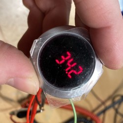
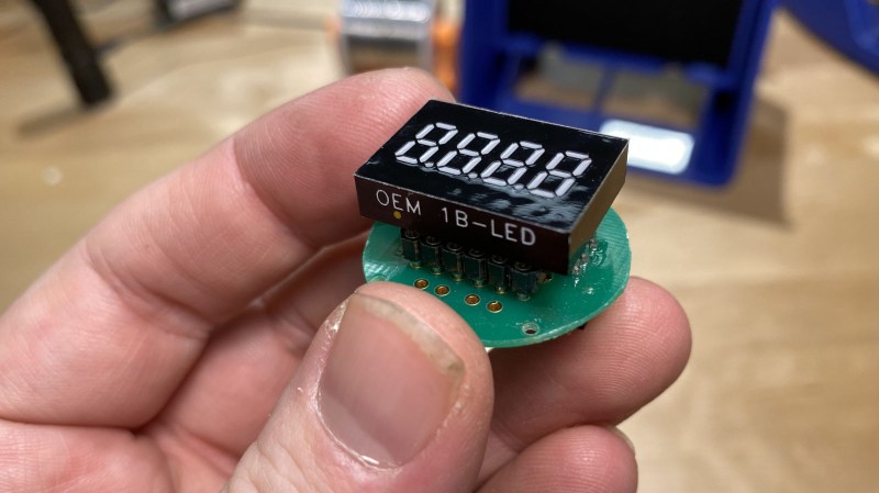
[JGlass] deals with public-facing technology, which he says includes things like theatre equipment, retail displays, and museum displays. Many of these pieces of technology are literally one-of-a-kind devices, even if they were constructed from what was once off-the-shelf, commercially available parts. When these machines need servicing, replacement parts aren’t always available, and reverse engineering comes in handy. He recently began documenting exactly how to approach this process by using the identification and replacement of an obsolete 7-segment industrial display as an example.
 The particular part shown is the Lascar EM32-4-LED, which up and died in a unique piece of equipment. The trouble is that the EM32-4-LED is out of production and unobtainable, and the Programmable Logic Controller (PLC) that drives the whole thing is a black box that cannot be modified. It’s very good news that a datasheet exists, but that’s often just a starting point. To create a one-off, drop-in solution requires a combination of research, troubleshooting, and design work.
To do this, [JGlass] starts off by walking through datasheet elements and explains that it’s important to build a high level understanding of function first, then drill down into details, and always be ready to verify, challenge, or throw out one’s assumptions. After establishing a high level understanding comes matching physical evidence to things like block and functional diagrams, then cracking open the faulty component to see if anything else can be learned. Only then are multimeters and probes taken out for more active research. All of this sleuthing must always be done with the end goal firmly in mind: creating a new device that acts like the one being replaced. Without focus, one can easily get lost in details and unknowns.
Reverse Engineering is a process, and the more tools, the better. If you missed our earlier post about a hacker’s guide to JTAG, here’s your chance to check it out and be all the more prepared for the next time you need to do some electron detective work of your own.


My son in laws hot tub went out . The main parts seemed to be working so it seemed the control board was blown, no way to be sure without replacing it. So i built a control board using and arduino which did the basic functions of the control board and now he has an hot tub again. The technical documentation was very limited but with some testing it was figured out.
Write the process out in a blog and submit it to here. I’d read about that! How did the Arduino control the main board etc?
I’ll second a request for a HaD article on this one, sounds quite interesting. Hoping it doesn’t fall on Def ears and you’ll consider writing it up with a few photos!
Thanks I will consider that. figuring out the controller board was a mess, so I just threw it away and controlled the pumps heater etc directly and read the temperature sensors directly. Did loose the ability to read the temps directly, thought of sending it to an app through an ESP32 or something, but got lazy. I will think about it a bit.
once when I was young and poor, we had a washing machine’s mechanical switch timer thingie go out, we ripped apart the control panel and installed a row of several switches connecting all of the various devices and polarities possible to a bunch of toggles, we found out how to control all of the functions of the machine by switch sequence, we did manage to preserve the fill sensor, and used a relay to make sure it never overflowed. but it was great! doing laundry went from a mundane task to something akin to flying the Apollo Lunar lander, it was hilarious, we had entire sequences written out to do all the things to do a load of laundry, we even scavenged a timer switch for a bathroom fan so we could make the machine shut off on its own if we walked away from it. had to show my friend once how to do laundry in it and he laughed the whole time, gave him the “manual” and ended up having to call me to get it started, it was all like “Houston we have a problem” all over again. 10/10 would do again, ( my wife might kill me for it though)
congrats so sounds like me
Oh man that sounds great, do you happen to have pictures?
We have something in common! I have a lascar volt meter that up and died on me. I have a spare, but I’m afraid it’ll do the same thing the first one did. It was on a golf cart and at the time it was the only low-draw self powered meter I could find.
It appears the back-emf killed it.
Author here, feel free to drop questions!
I’ve got a handful more installments in this series that I still mean to write up at some point, namely:
-using a logic analyzer to investigate the waveforms coming from the PLC
-building a display emulator in python to verifying that I had successfully decoded the bitstream
-building an Arduino-based LED-driver to create a new replica display from scratch.
I guess I should probably get working on those huh?
I’d love to know what the complication to interfacing with the PLC program is. Is it a locked program? or just too expensive to get the appropriate software? You seem more than capable of figuring out how to communicate with any model I’ve experienced.
Looks like you can rebuild the module in question. Going by the markings on the side of the LED looks like a few places still have them. Why was this not the route you took?
https://www.digikey.com/product-detail/en/lascar-electronics/OEM-1B-LED/2136-OEM1B-LED-ND/10259116
https://www.testequipmentdepot.com/lascar/panel-meters/compact-led-voltmeter-8-mm-oem-1b-led.htm
The LASCAR 1B-LED has a similar form factor, but it’s panel voltmeter. The EM-32-LED display that I’m replacing (or the OEM-32-LED inside it) is a 4-digit 7-segment display module that allows for direct control of each of the 35 display segments.
We actually have both types of modules in the space I’m working in, looks like I just put the wrong picture in the post. Oops!
I just reverse-engineered a PAL using just the machine’s schematics and relatively little trial&error.
Spoiler alert, the PAL has two simple independant functions: Be a BCD to 7 segment decoder with a very custom enable logic and using one pin more of said logic to trigger a Latch IC (74LS273). But today I’m going to test the latest version of my JEDEC file (the last one had a few errors, but basically worked) and this will allow a series of rare pinball machine displays to work again.
(these displays have Sloppy Designer Disease: they drive 16 light bulbs with an LS273 plus ULN2804 each 8. Every time, one bulb blows, there’s a chance of a split second short circuit, which shorted out the ULN and melted (no kidding, even the socket was melted) the LS273, the PALs were cracked in the middle and the segment strobe multiplexer, even though it looked fine, was completely fried inside, too) <- reminds me of that story of a light bulb killing a microwave which I also read on Hackaday (Note to editors: link in the article. I'm lazy, too)
There's another PAL in the CPU board, but I doubt it does anything else than Chip Selects.
This is great, i’ve recently encountered problems like this in repairing early 1990’s test equipment. Things like the linear regulator IC’s are no longer available but there are tricks that can be done to make them work again, or make something work again well enough.
The controller in those Lascar displays is a MM5450 die with all 41 pins available and used. Since DIP packages do not allow 41 pins, this die exists in 2 versions: MM5450 and MM5451.
But you could sacrifice the L4 output of the module by using a MM5450 so that the Enable (E) input remains accessible.
Microchip sells those chips in a DIP or PLCC package, and apparenty also bare die.
Interesting! I hadn’t considered gutting the OEM module itself and putting a new controller in it… perhaps when the world spins back up again that would be something I could do. Or spinning up an eternal module using a MM5450 in maybe DIP form factor and wiring it into a salvaged display.
Thank you!