We’ll be honest right up front: there’s nothing new in [David Cambridge]’s brushless motor and controller build. If you’re looking for earth-shattering innovation, you’d best look elsewhere. But if you enjoy an aimless use of just about every technique and material in the hacker’s toolkit employed with extreme craftsmanship, then this might be for you. And Nixies — he’s got Nixies in there too.
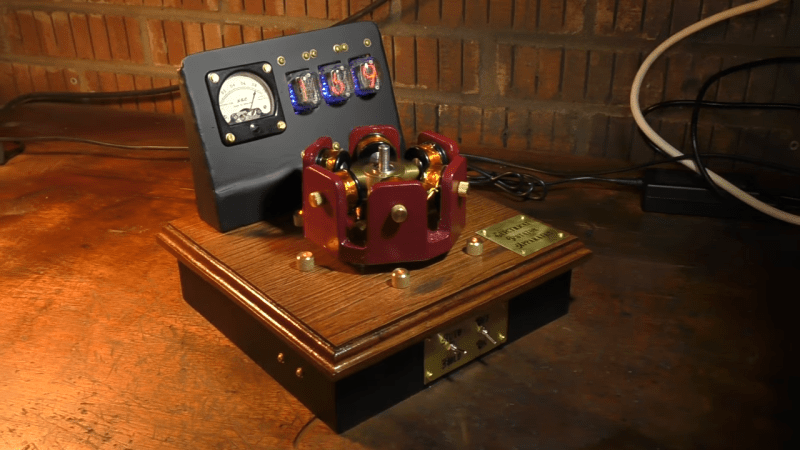
[David]’s build started out as a personal exploration of brushless motors and how they work. Some 3D-printed parts, a single coil of wire, and a magnetic reed switch resulted in a simple pulse motor that performed surprisingly well. This morphed into a six-coil motor with Hall-effect sensors and a homebrew controller. This is where [David] pulled out all the stops on tools — a lathe, a plasma cutter, a welder, a milling machine, and a nice selection of woodworking tools went into making parts for the final motor as well as an enclosure for the project. And because he hadn’t checked off quite all the boxes yet, [David] decided to use the 3D-printed frame as a pattern for casting one from aluminum.
The finished motor, with a redesigned rotor to deal better with eddy currents, joined the wood and metal enclosure along with a Nixie tube tachometer and etched brass control plates. It’s a great look for a project that’s clearly a labor of self-edification and skill-building, and we love it. We’ve seen other BLDC demonstrators before, but few that look as good as this one does.


At times I sit thinking by myself about why brushless motors using vacuum tubes for control never took off as early as it could have…
Like tubs can control very high currents and voltages, so seems fairly ideal as a switching device to be fair…
Not to mention that they are fairly immune to the typical inductive kickback able to kill fets. (or at least I can’t see much of a failure point in this regard at least.)
Maybe it were just the thought of having a whole bunch of tubes for running a “simple” motor that scared people away, when a trivial gearbox can achieve similar end results, especially if tied together with a CVT…
But that is a projects that would be fun to see, a tube based VFD. I can’t see much reason why it couldn’t work. (practicality wise is a different story.)
Now I know that the project of this article isn’t even remotely about a tube based VFD, but such a device would still be an interesting sight.
Older CNC/NC machines would have servo amplifiers utilizing tubes for driving motors/spindles akin to VFD (definitely not all machines). I’ve never had to work on anything that old myself, but you’re right about with the power requirements, it’s like, why not?
Tubes could not in fact run very high currents. High voltages, yes, but the high currents would erode the plates/grids very quickly.
Lets just put a few of them in parallel then.
With a good mechanical assembly, then hot plugging them should be relatively easy as well. In case one does burn out.
Maybe that’s part of the reason – reliability. How often would a tube burn out when applied in such an application?
I have a power pentode, GU-81M (as in Military Grade), it’s a transmitter tube. Max anode voltage is 3kV, max current is 600mA, and it takes 124W just to heat up the cathode. It’s the size of a big jar, and is guaranteed to work for mere thousand hours. Imagine making a BLDC or any motor driver/controller using such tubes, or even connecting many of them in parallel just to get enough current going. And the size of the thing, heat management, etc. would make it completely unpractical. Mechanical switches, relays, rheostats and thyratrons were a better option…
Incidentally, there were vacuum tube rectifiers used for high voltage DC transmission lines, and they employed liquid mercury as one of the electrodes, exactly because it would return back to liquid and the electrode would heal after each cycle of high current.
Not true in the least bit. But tubes that can handle high currents do tend to be expensive and big. For reference, the highest power triodes I’ve seen could handle 100+A at 160 kV for a good few seconds. And I’ve got some thyratrons in the garage that can handle many, many kA at about 35kV – just not for long. The reason for still using them in Pulsed Power work is they often handle faults quite well – and can deal with boat loads of radiation.
We’re talking of continuous high currents required for switching a motor for thousands of hours, nof “a good few seconds”.
Just about anything can take 100+ Amps – once.
the high currents would erode the plates/grids very quickly
Plates tend to run hot at high current, true, but the limit on high power tubes is generally the cathode: ripping high current density out of thoriated cathodes tends to degrade them rapidly. And plain (unthoriated) filaments just can’t produce the current density needed without melting.
Tube-based VFDs, specifically thyratron cycloconverters, were used in the 1930s for high-power motor control. Mentioned in, for example, Modern Power Electronics and AC Drives (Bimal K. Bose, 2002)
Thyratrons can deal with a lot of current, but they’re a pain to control because they behave the same as SCRs – they latch on until the current reverses. Doing variable frequency is incredibly complicated when you can’t turn your switch off as desired, so most thyratron based controllers are fixed frequency chopping circuits, much like light dimmers.
Thyratron and SCR-based cycloconverters were pretty much the only way to do frequency conversion without a motor-generator set. When used with a 3-phase supply it works well — and nothing at all like a light dimmer.
I’d like to see the circuit. Do you have a diagram?
Ah, I see, so the cycloconverter synthesizes a maximum frequency of 1/2 the input AC frequency by selecting which bits of the three phase input currents are directed to the load and for how long.
So it is depending on the input waveform to go to zero to shut down the SCR/Thyratron. That’s different from what a modern VFD does – which generates an arbitrary frequency even above the line frequency to drive the motor. To get equivalent function with a cycloconverter would be complicated indeed.
To understand how a cycloconverter works, you can think of an AC-DC rectifier that can select which way it works. An example of a single-phase cycloconverter:
https://www.electrical4u.com/wp-content/uploads/cycloconverter.png
Three phases gets you a little more finesse, but it’s the same principle. It’s basically an SCR chopper that works both ways to change the polarity of the output current, so it can generate a crude AC signal at some fixed fractions of the input AC waveform.
True, thyratrons (and later thyristors) need to be commutated by a zero crossing, but that can be provided by the load: This is commonly done by HVDC converter and grid intertie (including 50/60Hz conversion) stations at hundreds of megawatt scale. It does require a synchronous or resonant load, and isn’t self-starting, but it’s very commonly done.
True, that has been my experience with them also.
I was a recording engineer in the day of 16 and 24 track Ampex machines. If we wanted to run the tape at a variable speed, we’d drive the capstan motor from a Macintosh audio tube amplifier. You’d know that you’d set the gain properly when the plates started to glow a warm cherry red. Worked great.
3D printing, electronics, PCB design, programming, WELDING, wood working, machining, casting … holy cow this guy does everything!
All that nice work and then ruin it with blue LEDs… Inconceivable.
….That and the Nixies. I love Nixies, by the way… but they don’t belong here. When I see them, I think Cold-War launch counter, not Steampunk.
Aesthetics aside, great work.
Personally I think the Nixies would’ve worked better with the overall aesthetic if they weren’t mounted in that block box. Seems a bit at odds with the rest of the parts, but still a beautiful project.
You should check out the last few seconds of the video.
I see blue LEDs underlighting Nixie’s often, who thought that was a good idea?
I have no idea. I see them in there nearly every time. And blue lights under vacuum tubes in audio amps. It’s frustrating. What’s wrong with a regular orange glow? I blame gamer computer cases for this particular form of kitsch.
It could have been a really good project if only he’d stuck an Arduino in it.
Jeebus, who’s this guy. Some kind of renaissance man?
Nice!
Nikola Tesla would have been quite please with an assistant like this guy. That’s some spectacular skills in a topnotch workshop. Very inspiring.
That’s how high current valves looked like. A bit scary, but definitely steampunky :-)
https://en.wikipedia.org/wiki/Mercury-arc_valve
Yesss. Can’t erode the cathode as badly if the cathode is a liquid. I remember finding a few of these deep in the NYC subways.
These are basically vacuum diodes, not switches.
Is so pretty. Gorgeous steam gauge analog sweep meter but Nixies should have been harmed. Going to use that style of lettering and brass should be accompanied by copious filigree. All the essential fancy equipment but lacking the most basic of rigs like a router table or railed sled guide for plasma cutter. Huh. Guage panel itself meh. Black paint only goes so far and at a distance. Hiding the real artwork of PCB seems wrong. Took the time and pretty flashing lights and then shove underside.
Nit picking.
Hmmm, I’m calling shenanigans… I had one of those exact same gauges back in the day and mine was date stamped 1942 making this dieselpunk era.
Wouldn’t steam punk motors be running on steam?
I prefer to run my motors on punks. When they try stop, a shot of steam gets ’em running again.
I’m partial to amphetamine-fueled punks myself. If you get more flies with honey than vinegar, imagine all the flies you can get with amphetamines.
You might also look into odd numbers of poles as even number of poles can cause stalls.
This was a problem they solved with old radial engines in planes. See https://en.wikipedia.org/wiki/Radial_engine
Magnets can’t have odd numbers of poles. Even if you have an odd number of magnets, they will form a combined field with an even number of poles.
Really? I had not known that. I will have do research it. Thanks!
It kinda comes as given. Magnets have two poles, and by alternating north and south around the motor perimeter, you can have one pole-pair, two pairs, three pairs, four pairs… but never a pair and a half. That’s because when you put three magnets around the circle and try to have S S N or N N S, it’s simply the same two poles, only one pole becomes bigger.
The outer ring are elctromagnets, and get switched on and off. I was talking about making the outer group odd numbered, not the inner permanent magnets.
i envy his skills and tools..
It was a suprise that cable management was overlooked, other than that, awesome execution!
btw i am a ratsnest guy, often leaving my pcbs to live in their ratsnest as case..
Awesome work. 🏆💯 ☑️
Thanks for sharing. 😉👌🏼
tell us about your camera based microscope for seeing your small solder work.